Question and answers
| Que.No | Marks | |
|---|---|---|
| Q 3 d ) |
4 |
Question:Name any four components of pneumatic system. What are the factors considered while selecting them ?Answer: 1) Compressor: a)Pressure Requirement b) Volume of Air c) Compressor configuration 2) Actuators: a) According to maximum pressure b) According to application – Linear/Rotary c) shape and size of actuator 3) Air Receiver: a) Storage capacity b) Material of the tank 4) FRL unit: a) According to working environment b) According to pressure required at hand tools 5) DCV: a) According to maximum pressure of system. b) According to actuator configuration c) According to application- One hand /Two hand d) According to actuation method suitable for application ----------------------------------------------------------------------------------------------------- |
| Q 3 e ) |
4 |
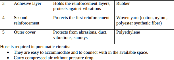
Question:Draw labelled sketch of air lubricator.Answer:
|
| Q 4a)(b) |
4 |
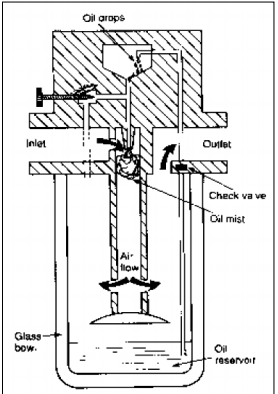
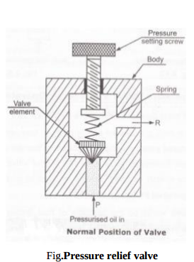
Question:Explain pressure relief valve in pneumatic system.Answer:
The pressure relief valves are used to protect the system components from excessive pressure. Its primary function is to limit the system pressure within a specified range. It is normally a closed type and it opens when the pressure exceeds a specified maximum value by diverting pump flow back to the tank. The simplest type valve contains a poppet held in a seat against the spring force as shown in Figure. This type of valves has two ports; one of which is connected to the pump and another is connected to the tank. The fluid enters from the opposite side of the poppet. When the system pressure exceeds the preset value, the poppet lifts and the fluid is escaped through the orifice to the storage tank directly. It reduces the system pressure and as the pressure reduces to the set limit again the valve closes. ( Pressure switch in Pneumatic or Pressure relief valve in hydraulic system can be considered) ----------------------------------------------------------------------------------------------------- |
| Q 6 b ) |
4 |
Question:State any four reasons of failure of pneumatic seals.Answer: 1. Incompatibility of seal material with operating system 2. Excessive heat 3. Excessive load 4. Excessive clearance 5. Excessive pressure 6. Improper fitting 7. Improper groove geometry 8. Abrasion 9. Wear ----------------------------------------------------------------------------------------------------- |
| Q 6 b ) |
4 |
Question:State any four reasons of failure of pneumatic seals.Answer:
|
| Q 6 c ) |
4 |
Question:(c) What are the advantages of pneumatic system over hydraulic systems ?Answer:
|
| Que.No | Marks | |
|---|---|---|
| Q 2 b ) |
8 |
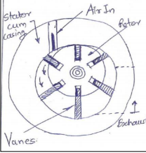
Question:List various types of air motors. Explain vane type air motor with neat sketch.Answer: Various Types of Air Motors 1. Vane Motor 2. Gerotor Motor 3. Turbine Motor 4. Piston Motor Construction: It consists of simple Vane rotor which is having slots in which vanes (flat piece of steel) slides freely. The rotor is eccentrically located inside the stator housing. Working: When pressurized air comes in through inlet port, the pressure of air distributes equal in all directions. Since vane is sliding freely in slots of rotator, the vane comes in to way of pressurized air and air pushes the vanes so that rotor starts rotating with speed. The used low pressure air is exhausted through exhaust port. This is unidirectional motor. Since vanes are freely sliding in slots, there is possibility of leakage of air. With the help of these motors we can achieve the speeds up to 25000 r.p.m.
|
| Q 3 e ) |
4 |
Question:What is FRL ? State the function of each component of FRL.Answer: FRL Unit: It is service unit used in Pneumatic system which is combination of three devices named as Filter, Regulator and Lubricator. Function of FRL unit Filter (F) – 1) To remove the micron and sub-micron particles present in the entering air of compressor. It is Used to separate out contaminants like dust, dirt p[articles from the compressed air Regulator (R) – In pneumatic system the pressure of compressed air may not stable due to possibility of line fluctuation. Hence there is a need to maintain and regulate the air pressure. This function is performing by regulator. Lubricator (L) – Sliding components like spool, a pneumatic cylinder has sliding motion between parts. It may cause friction and wear and tear at mating parts. To reduce friction, lubricating oil particles are added in the compressed air with the help of lubricator. ----------------------------------------------------------------------------------------------------- |
| Q 4a)(b) |
4 |
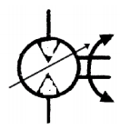
Question:List any four applications of pneumatic rotary actuator. Draw the symbol for variable speed bidirectional air motor.Answer: In all pneumatic power tools like screw drivers, angle grinders, straight grinders. To rotate conveyor belts in food industry. Power device in printing press machine Agitators and mixers Vibrators. symbol for variable speed bidirectional air motor
|
| Q 4a)(c) |
4 |
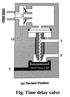
Question:What is the Function of Time Delay valve?Answer: Time delay valve functionTime delay valve function need:Time delay valve function : In certain applications like machining or press operation it is necessary that certain operation be delayed by some fraction even after pressing valve. This objective is achieved by Time delay valve. Time delay valve function working:Time delay valve is a combination valve used to set the operation time as per the requirement. The time delay can be increased or decreased by adjusting the flow through the non-return flow control valve. The change invariably increases or decreases the time taken to fill and pilot actuates the direction control valve. Time delay valve is a combination of a pneumatically actuated 3/2 direction control valve, an air reservoir and a throttle relief valve. The time delay function is obtained by controlling the air flow rate to or from the reservoir by using the throttle valve. Adjustment of throttle valve permits fine control of time delay between minimum and maximum times. In pneumatic time delay valves, typical time delays in the range 5-30 seconds are possible. The time delay can be extended with the addition of external reservoir. Time delay valve, NC type. The constructions of an on-delay timer (NC) type in the normal and actuated are shown in Figure It can be seen that 3/2 DCV operates in the on delay mode permanently. But, in some designs, the valve can be operated in the off-delay mode by connecting the check valve in reverse direction. Time delay valve is shown in diagram below. Time delay valve function diagram:Pneumatic time delay valve is used when time based sequencing is required. Construction and symbol of valve is shown in figure below. It is simply a 3/2 direction control valve, which is impulse operated from one side. Time delaying is achieved by delaying the impulse actuation. The valve has an in-built air reservoir and in-built non-return flow control valve. When impulse is applied to port “Z” for valve actuation, the air passes through needle control valve, which controls the rate of flow, further the valve spool is not actuated until the air reservoir is filled completely and pressure is built-up. (This time difference between impulse application at “Z” and actual spool actuation is the “delay”, which is adjustable through needle valve). This valve is found applicable in time based sequencing, which is common industrial application, e.g. clamping, indexing, feed motions etc.
ALTERNATE DIAGRAM
==================================================== Time delay valve function additional information and Diagrams are given below. ----------------------------------------------------------------------------------------------------- |
| Q 4a)(d) |
4 |
Question:Draw speed control pneumatic circuit for bi-directional air motor.Answer:
Fig. Speed control of bi-directional air motor Bi-directional air motor rotates in clockwise as well as anti-clockwise direction. The speed of bidirectional motor is controlled as shown in fig. The speed control of motor by using variable two flow control valves having built-in check valve and 4x3 DC valve having zero position or central hold position with lever L1 and L2. When lever L1 is operated, port P will be connected to port A of air motor and motor will start rotating in clockwise direction. Its speed can be controlled by using variable flow control valve F1. Port B of motor will be connected to exhaust R and air in motor will be exhausted through port R via DC valve. When lever L2 is operated, pressure port P will be connected to port B of motor and naturally motor will start rotating in anticlockwise direction. Port A will be connected to port R and air in the motor will be exhausted through port R via DC valve. ----------------------------------------------------------------------------------------------------- |
| Q 5 a ) |
8 |
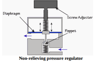
Question:List different types of pressure regulator valves ? Explain any one with neat sketch.Answer: Pressure-relief valve.Pressure-reducing valve. Unloading valve Counterbalance valve Pressure-sequence valve Brake valve.
Working: The compressed air pressure from FRL unit acts against the poppet (valve element) through inlet of pressure relief valve. When the force of air is greater than the spring force then poppet gets lifted from the valve seat and valve opens. Thus the excessive pressurized air will get release to the atmosphere through port R. (03 marks) OR Pressure regulation in pneumatics is vital for the correct operation of circuits and for damage prevention to circuit components. As you would imagine all pneumatic components have a maximum operating pressure. Types: A) According to no. of stages Single stage and two stage regulator B) According to pressure relief Non- relieving type and relieving type pressure regulator Non-relieving pressure regulator Non-relieving pressure regulators work by restricting flow rather then venting it should over pressure occur. The regulator restricts flow when the pressure gets too high because the pressure acts on the diaphragm forcing i t up against the spring pressure, the diaphragm has what is called a ‘poppet’ attached on the end of it which is drawn up with the diaphragm and restricts the passing air flow.
|
| Q 6 a ) |
4 |
Question:State at least four advantages and disadvantages of pneumatic systems.Answer: Pneumatic system Advantages DisadvantagesPneumatic system Advantages Disadvantages are given in details below. Pneumatic system Advantages1) Infinite availability of the sourceAir being freely and easily available everywhere there is no scarcity of the source. Just need some filtration for its use in the pneumatic system. As compared to the Hydraulic oil it is very cheap. 2) Safe and cleanAs compared to hydraulic and other systems air is very safe and clean in operation. Food industry, pharmaceuticals industry ect. prefer pneumatic system over other because leakage of air doesn't causes any issues. The system is relatively clean , no dirt accumulates due to oil leakage like in hydraulic system. 3) Less Operating and Maintenance costPneumatic system operates with very less resources and is easy to maintain. 4) The transfer of power and the speed is very easy to set up .The speed and power is controlled by pressure and flow of air, which can be easily controlled by knobbed controls. Just varying the pressure changes the force and varying air flow changes the speed of the actuator. 5) Can be stored and Easy utilized .Compressed air can be easily stored in a reservoir tank. It retains its pressure over long time. Also it is harmless even it leakages. Pneumatic System Disadvantages1) Requires installation of air-producing equipmentEvery pneumatic system needs constent supply of compressed air, which is produced by a compressor. 2) Can easily leakLeakage of air is one of the main issue in pneumatic system. Air can easily leak from the joints and threadings. 3) Potential noiseExhausting air produces large noise as compared to other power transmitting systems. 4) Low operating pressureAs compared to Hydraulic system where the pressure above 500 bar is possible to produce, pneumatic system max pressure is limited in most cases to 10-20 bar. Hence very heavy work can not be done with pneumatic system. ----------------------------------------------------------------------------------------------------- |
.png)
| Que.No | Marks | |
|---|---|---|
| Q 1a)(iii) |
4 |
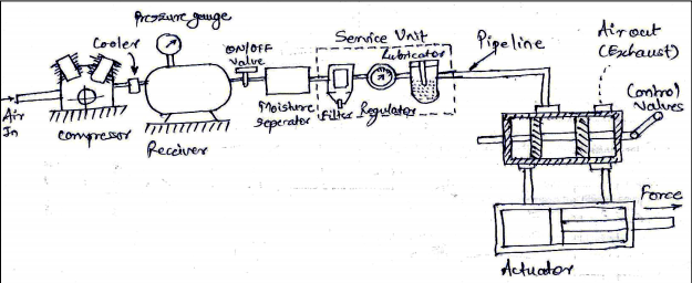
Question:Draw a general layout of pneumatic system and state the function of componentsAnswer:
1) Air inlet filter – Free air from the atmosphere enters the compressor through an air-inlet filter which will essentially keep out the dust and dirt from entering the system. 2) Compressor: It is used to compress the air from atmosphere pressure to the desired higher pressure level. It can be single stage or multistage in operation. 3) Cooler: Removes the heat generated during the process of operation. 4) Pressure switch and control unit: Maintains the pressure in the receiver in the predetermined range by starting and stopping the prime mover. 5) Moisture separator: Cooling air in the cooler results in condensation of vapor in the air. The condensate in the form of water droplets are separated from air. 6) Service unit: Filter – Separates sub-micron level contamination. Regulator – Bring the pressure of air from receiver pressure to the device pressure. Lubricator – Adds lubricants to air. 7) Pipe Line: They carry the compressed air from one location to another. 8) Control Valves: They are required to control the air direction, pressure and flow rate. They are responsible for the smooth and precise control of the pneumatic actuator, and also for the safe operation of the system. 9) Actuator: They will convert the high pressure energy of the compressed air into mechanical force or do useful work. Actuators can either be pneumatic cylinders to provide linear motion or pneumatic motors to provide rotary motion. ----------------------------------------------------------------------------------------------------- |
| Q 2 c ) |
8 |
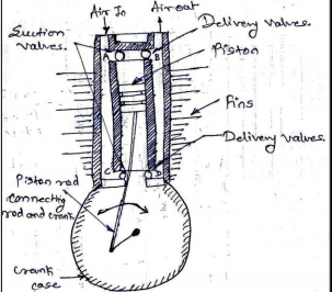
Question:Explain the construction and working of doubled acting reciprocating compressor with neat sketch.Answer: Double acting reciprocating air compressor is similar to double acting reciprocating pump. It is comprised of following parts: 1) Cylinder 2) Piston and piston rod and connecting rod. 3) Crank and crank case 4) Two suction valves and two delivery valves. 5) One inlet port and one outlet port It uses four bar mechanism. There are 4 valves (2 suction valves and 2 delivery valves) shown at A, B, C, D in figure. There are cooling fans similar to single acting compressors. The crank rotates on electric motor/engine/turbine. In this compressor, compression of air takes place on both side of the piston. When crank rotates, the piston starts reciprocating. When piston comes down and attains, ‘Bottom dead center piston’ the air comes in through port ‘A’ due to vacuum created due to downward movement. When piston starts moving upward, the air starts compressing. When piston attains, ‘Top dead center piston’, the stroke is complete and air is fully compressed which goes out through delivery valve ‘B’ to air receiver. During this upward movement the vacuum is created on other side (Piston rod side) of piston. Suction valve ‘C’ opens and air comes in. When piston starting comes down, this air which came through valve ‘C’, gets compressed and compressed air goes out through delivery valve ‘D’ to air receiver. In this downward movement air comes in through valve ‘A’ and entire cycle repeats.
|
| Q 3 d ) |
4 |
Question:What is FRL unit? Explain its functionAnswer: FRL unit means Filter Regulator and Lubricator Unit Function of FRL unit Filter (F) – 1) To remove the micron and sub-micron particles present in the entering air of compressor 2) Used to separate out contaminants like dust, dirt particles from the compressed air Regulator (R)–In pneumatic system the pressure of compressed air may not stable due to possibility of line fluctuation. Hence there is a need to maintain and regulate the air pressure. This function is performed by regulator. Lubricator (L) – Sliding components like spool, a pneumatic cylinder has sliding motion between parts. It may cause friction and wear and tear at mating parts. To reduce friction, lubricating oil particles are added in the compressed air with the help of lubricator ----------------------------------------------------------------------------------------------------- |
| Q 4a)(iii) |
4 |
Question:What are the limitations of pneumatic system?Answer: 1. Relatively low accuracy: As pneumatic systems are powered by the force provided by compressed air, their operation is subject to the volume of the compressed air. As the volume of air may change when compressed or heated, the supply of air to the system may not be accurate, causing a decrease in the overall accuracy of the system. 2. Low loading: As the cylinders of pneumatic components are not very large, a pneumatic system cannot drive loads that are too heavy. 3. Processing required before use Compressed air must be processed before use to ensure the absence of water vapour or dust. Otherwise, the moving parts of the pneumatic components may wear out quickly due to friction. 4. Uneven moving speed: As air can easily be compressed, the moving speeds of the pistons are relatively uneven. 5. Noise: Noise will be produced when compressed air is released from the pneumatic components. 6. Lubricator: Lubricator is required to add lubricant oil to compressed air to reduce friction. ----------------------------------------------------------------------------------------------------- |
| Q 4b)(i) |
6 |
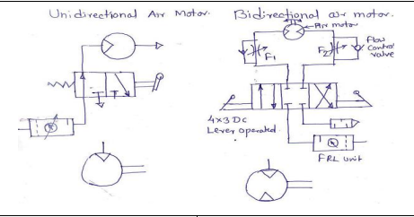
Question:What is the meaning of unidirectional air motor and bi directional air motor? Explain with sketch and draw symbol of bothAnswer: Operating or moving or allowing movement in one direction only. It runs in one direction only. It does not run in the other direction. Unidirectional motor can be operated by using 3/2 DC valve as shown in fig. Bidirectional air motor: Functioning or allowing movement in two usually opposite directions. It can runs in both direction. Bi-directional motor can be operated by using 4/3 DC valve as shown in fig
|
| Q 4b)(ii) |
6 |
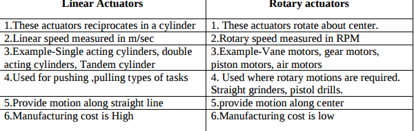
Question:Compare linear actuators and rotary actuators.Answer:
|
| Q 6 d ) |
4 |
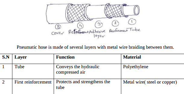
Question:Draw constructional details of pneumatic hose. Why hose is required in pneumatic circuits?Answer:
|