Question and answers
| Que.No | Marks | |
|---|---|---|
| Q 1a)(b) |
4 |
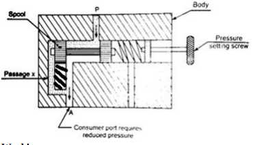
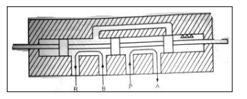
Question:Draw and explain working of pressure reducing valve.Answer: Draw and explain working of pressure reducing valve. The main function of pressure reducing valve is to reduce the pressure in particular branch of the circuit to different level as demanded by consumer in that branch. Construction: It consists of spool and spring housed in the bore of valve body. Spring compression can be adjusted by pressure setting screw. Port P is pressure port connected to pump. Port A is consumer port requiring reduced pressure.
Working: As shown in normal position, port P is supplying oil to consumer port A. If the main supply is below the set pressure, there will be continuous flow from P to A. Hence normally this valve is open. When outlet pressure rises to valve setting then oil will flow through ‘passage x’ and will act on spool and spool will shift to right thereby partly closing the port A. Now only enough flow will pass through port ‘A’ so that consumer connected to A will receive reduced pressure. ----------------------------------------------------------------------------------------------------- |
| Q 1a)(d) |
4 |
Question:What is an accumulator ? Why accumulator is necessary for huge hydraulic pressers ?Answer: makes available to the system whenever required. Necessity of accumulator for every huge hydraulic press: Oil requirement of the system is not continuous but intermittent. A hydraulic press needs the oil only during the lifting operation. While, during the lowering of load, holding the load or during idle period, it doesn’t not require any supply of oil. During such period, the hydraulic pump has to stop or delivered oil must be drained back to the sump. But frequent starting and stopping of pump is not desirable as it reduces the pump life. Also, draining the pressurized oil is wastage of power which reduces the system efficiency. The remedy to above problem is to use accumulator in the system. ----------------------------------------------------------------------------------------------------- |
| Q 1b)(a) |
6 |
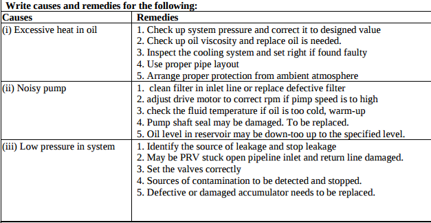
Question:Write the causes and remedies for the following : (i) Excess heat in oil (ii) Noisy pump (iii) Low pressure in system.Answer:
|
| Q 1b)(b) |
6 |
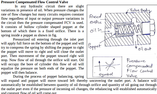
Question:What is pressure compensated flow control valve ? Explain with sketch.Answer: In any hydraulic circuit there are slight variations in presence of oil. When pressure changes the rate of flow changes but many circuits requires constant flow regardless of input or output pressure variations in the circuit then the pressure compensated FCV is used. It consists of hollow cylinder shaped poppet at the bottom of which there is a fixed orifice. There is a spring inside a poppet as shown in fig. Pressurized oil entering through the inlet port will apply full force on the bottom of the poppet and will try to compress the spring by shifting the poppet to right the poppet will move to right and will close the outlet port. Then movement of the poppet toward right will stop. Now flow of oil through the orifice will start. Oil will occupy the bore of cylinder this flow of oil will equalize the pressure on both ends of the poppet. The poppet will then balance. During the process of poppet balancing, spring will expand and poppet will move toward left thereby uncovering the outlet port. A balance will automatically be established between quantity of oil through orifice and quantity of oil going out through the outlet port even if the pressure of incoming oil changes, the rebalancing will established automatically and constant flow of oil will come out
----------------------------------------------------------------------------------------------------- |
| Q 2 c ) |
8 |
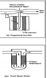
Question:What is function of filters ? Classify the filters and draw any two types of filtersAnswer: What is function of filters? Classify the filters and draw any two types of filters. Function of filter: To remove foreign particles from the oil and remove submicron particles dissolved in the oil. Classification of filters: 1- Full flow filter 2- Proportional flow filter Full flow filter: Incurs a large pressure drop. A relief valve is needed which cracks when the filter becomes blocked. Proportional flow filter: Localised low pressure area is formed at the venturi. The fluid is drawn from the filter due to the pressure difference. low pressure drop
|
| Q 3 a ) |
4 |
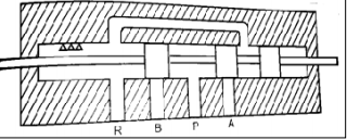
Question:Explain 4-way-3 position direction control valve used in hydraulic system.Answer: 4-way-3 position direction control valve used in hydraulic system is known as 4X3 DC Valve. The valve has four ports and three positions. Following figure shows the Normal and working positions of DCV. Spool of this valve is having three positions. The spool is so selected because we have to obtain third position also called as ‘Closed Centre Position’ This position is shown in figure. We have shifted the spool in such a manner that all ports are closed to each other. Mo flow from port P to port A or B and no flow from port A and B to R. When DC valve attains this position, pressured oil returns to reservoir via pressure relief valve. The closed center position of DC valve is suitable for immediate closing of movement of actuator. Position- I
Position- II
Closed center position
|
| Q 4a)(a) |
4 |
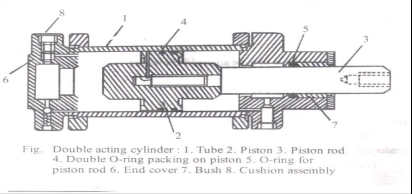
Question:What are actuators ? Draw a double acting cylinder.Answer: Actuator - Actuators are those components of hydraulic / pneumatic system, which produces mechanical work output. They develop force and displacement, which is required to perform any specific task. An actuator is used to convert the energy of the fluid back into mechanical power.
|
| Q 4a)(d) |
4 |
Question:State any two applications of 3 × 2 DC valve. Draw symbol for the same.Answer: To start, stop and change the direction of motion of a Single acting cylinder. (Clamping of Job)
|
| Q 4b)(b) |
6 |
Question:Compare pressure relief valve and pressure reducing valve.Answer: ----------------------------------------------------------------------------------------------------- |
| Q 6 e ) |
4 |
Question:What are the various types of Hoses used in pneumatic systemAnswer: Hoses are flexible connecting tubes or pipes to connect actuators, control valves. Different layers of hose 1) Inner tube 2) Reinforcement 3) Outer protective cover Hoses: are flexible vessels that are constructed of multiple layers of different materials. Fittings for hoses are often not permanent, since the hose itself is often replaced in time due to wear ----------------------------------------------------------------------------------------------------- |
| Que.No | Marks | |
|---|---|---|
| Q 1a)(d) |
4 |
Question:Explain any two mounting methods of cylinder.Answer: 1) Centreline mounting Centreline mounts are used to take care of thrust that can occur linearly or along a centreline with the cylinder. Proper alignment is essential to prevent compound stresses that may cause excessive friction and bending, as piston extends. Additional holding strength may be essential with long stroke cylinders. 2) Foot mounting It consists of mounting the cylinder with the help of side end lungs or side covers. These mountings are used where cylinders are to be mounted on to surface parallel to the axis of cylinder ----------------------------------------------------------------------------------------------------- |
| Q 1b)(b) |
6 |
Question:With a neat sketch explain pressure compensated flow control valve. Draw symbol of it.Answer:
|
| Q 2 b ) |
8 |
Question:Name any eight pipe or tube fitting with their application.Answer: 1) Adaptor – To connect two pipes of different diameters. 2) Coupling- To connect two pipes of same diameters. 3) Tee- To connect two pipes with one pipe. 4) Cross- To connect two pipes in crosswise. 5) Elbow- To divert the flow between two pipes at right angle. 6) Hex nipple- To connect two pipes internally with the help of hexagonal nut. 7) 450 Elbow- To divert the flow between two pipes at 450 angle. 8) Reducer- To connect two pipes of different diameters and it will increase or reduce the pressure of flow ----------------------------------------------------------------------------------------------------- |
| Q 2 c ) |
8 |
Question:What is seal ? Classify seals according to shape. State the factors for seal selection.Answer: Seal: The seal is an agent or element which prevents leakage of oil from hydraulic elements and protects the system from dust and dirt. Classification of seals based on shape:- a) ‘O’ Ring seal b) ‘V’ Ring seal c) U-packing seal d) T- ring seal e) Cup seal Factors for seal selection: 1) Type of fluid used in system 2) Maximum temperature of system in working condition 3) Functional reliability expected 4) Cost of seal 5) Working pressure of system 6) Environmental condition ----------------------------------------------------------------------------------------------------- |
| Q 3 b ) |
4 |
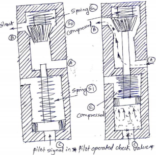
Question:Discuss pilot operated check valve with neat sketch.Answer: When pilot signal of pressurized oil is used to control movement of poppet in the check valve, it is called as pilot operated check valve. It is used when no flow characteristics of the valve is desired only for a portion of the system cycle. Figure shows the pilot operated check valve. A pilot piston is introduced below moving poppet. This pilot piston can move up by introducing pilot signal. Working: In normal position there is no flow from (A) to (B) because the movable valve poppet has blocked the flow. Now pilot signal is given through port (C). This oil will push up the pilot piston upwards, thereby compressing springs (S1). The piston rod of pilot piston will push the movable poppet in upward direction thereby compressing the spring (S2). Now the flow from (A) to (B) will start. As and when we cut-off the pilot signal the flow from (A) and (B) will continue. When pilot signal will be cut-off, spring S1 and S2 will expand and moving poppet will again block the flow from (A) to (B).
|
| Q 4a)(a) |
4 |
Question:State the four merits and demerits of using a rubber hose in pneumatic circuit.Answer: Merits: 1)Well equipped with quick connect or disconnect end fitting 2)Can be manufactured in long lengths 3)Capable of withstanding to very high pressures. 4)They can absorb very heavy shocks tha rigid tubes. Demerits: 1) Very poor in abrasion resistance 2) Poor in resisting whether condition. 3) Initial cost is very high 4) They can damage due to incompatible oil ----------------------------------------------------------------------------------------------------- |
| Q 6 b ) |
4 |
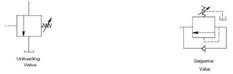
Question:Draw symbol of unloading valve and sequence valve.Answer:
|
| Que.No | Marks | |
|---|---|---|
| Q 1b)(ii) |
6 |
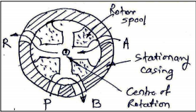
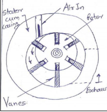
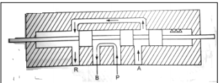
Question:Explain with neat sketch the working of rotary spool type DC valve.Answer: A rotary spool valve consists of a rotating spool which aligns with ports in stationary valve casing, so that fluid is directed to required port. A/B/P/R are the ports in casing. The port ‘P’ is a pressure port though which pressurized oil is coming in the valve. ‘R’ port is the port through which used oil is returning to oil tank. From fig port p is connected to port B and port A is connected to port R
|
| Q 2 a ) |
8 |
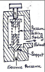
Question:Why pressure relief valve is used in hydraulic circuit? Explain in details with neat sketchesAnswer: Pressure Relief Valve used because; 1. To Maintain desired pressure levels in the circuit. 2. To set maximum pressure in hydraulic system. 3. Protect the pump and other system components from overloading. 4. It acts as a relief and safety device ExplanationSimple pressure relief valve is also a Direct operated pressure relief valve. It consists of Poppet, spring, pressure setting knob and valve body. It is normally closed valve connected between pressure line and the oil reservoir when inlet oil pressure is less than the spring force; it means that it is insufficient to overcome the spring force, the valve remains closed. The pressure of oil is safe for the system. When the oil pressure is greater than spring force, it pushes the poppet against the spring force and unseated the poppet. Now the valve opens and oil flow from inlet port to the reservoir. The valve will remain open until the excessive pressure is diverted to the tank. Cracking pressure: the pressure at which the valve first opens is called the cracking pressure. It is essential for every hydraulic system to provide pressure relief valve as a safeguard against the pressure.
|
| Q 3 b ) |
4 |
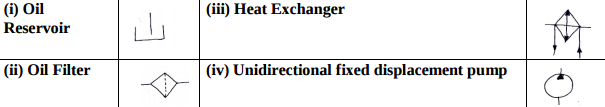
Question:Draw symbols of: (i) Oil reservoir (ii) Oil filter (iii) Heat exchanger (iv) Unidirectional fixed displacement pump.Answer:
|
| Q 4a)(i) |
4 |
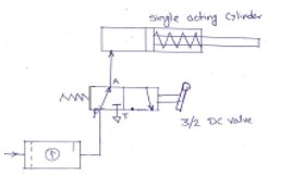
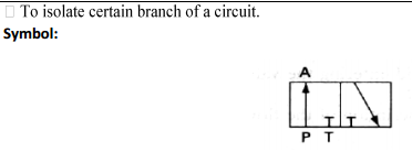
Question:What is the use of direction control valve? Explain with sketch.Answer: 1. DC valves are used to release, stop or redirect the fluid that flows through it. 2. DCV is used to control the direction of fluid flow in any hydraulic system and changing the position of internal movable parts. 3. To start, stop, accelerate, decelerate and change the direction of motion of a hydraulic actuator. 4. To permit the free flow from the pump to the reservoir at low pressure when the pump’s delivery is not needed into the system. 5. To vent the relief valve by either electrical or mechanical control. 6. To isolate certain branch of a circuit. The following circuit shows use of 3/2 DC valve. When the lever is operated, port A is connected to exhaust port ,i.e change in direction of the piston. (Alternative sketch can be considered)
|
| Q 4a)(iv) |
4 |
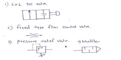
Question:Draw symbol of: 1) 2 × 2 DC valve 2) Fixed type flow control valve 3) Pressured relief valve. 4) MufflerAnswer:
|
| Q 5a)(i) |
8 |
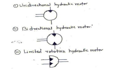
Question:Draw symbol of any three types of Hydraulic motors.Answer:
|
| Q 5 c ) |
8 |
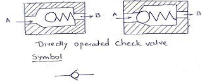
Question:Explain working of directly operated (Poppet type) check valve with neat sketch.Answer: When oil under pressure is supplied to port A, the oil exerts pressure on the ball against the spring force, hence the ball will be lifted off from its seat and creates a passage for
oil to flow. Hence oil can flow from port A to port B. when under pressure is supplied in opposite direction that is to port B, the oil force the ball to sit firmly in its seat, hence the passage is closed by ball. The oil cannot flow port B to port A. ----------------------------------------------------------------------------------------------------- |