Question and answers
| Que.No | Marks | |
|---|---|---|
| Q 2 a ) |
8 |
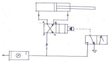
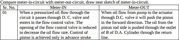
Question:Compare meter-in-circuit with meter-out-circuit, draw neat sketch of meter-in-circuit.Answer:
|
| Que.No | Marks | |
|---|---|---|
| Q 2 a ) |
8 |
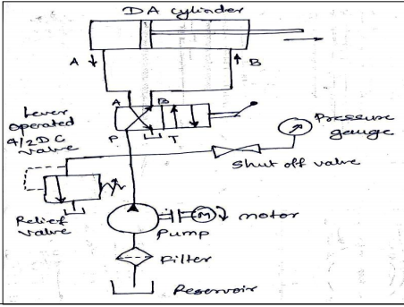
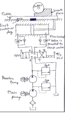
Question:Explain with neat sketch the working of hydraulic circuit for milling machine.Answer: Working of hydraulic circuit for milling machine. Hydraulic circuit for milling machine is comparatively different from other circuits. Table movement of milling machine is required to be adjustable for different feeds for different type of work. Therefore for both strokes of the cylinder, on both ends of cylinder flow control valves are used. Another feature of this circuit is that there are two pumps 1. Main pump – low pressure high discharge 2. Booster pump - high pressure low discharge The function of booster pump is to boost the hydraulic pressure to a higher level than given by main pump. Reason behind using this type is to save power as well as use of high pressure high discharge pump is avoided. 4/3 DCV used manually operated stroke length of cylinder is adjustable through limit switch. In centre position of 4/3 DCV all the ports are close therefore, total hydraulic system is lock.. position (I) pump flow is given to cylinder blank end and extension starts and oil from rod end is discharge to tank. In (II) position, pump flow diverted to rod end for retraction and blank end side flow pass to tank
|
| Q 3 a ) |
4 |
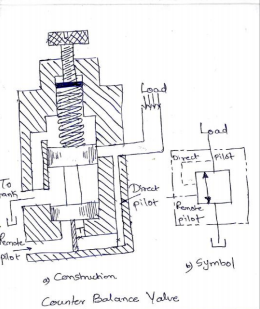
Question:Explain the working of counter balance valve in hydraulic circuit.Answer: Counter Balance Valve It is basically a relief valve but it is used to set up a back pressure in a circuit to prevent load from falling. They are frequently employed in vertical presses, loaders, lift trucks and other machines that must maintain a particular position or hold a suspended load. In such applications, the counterbalance valve creates a back pressure to prevent the movement of piston rod of cylinder Figure shows a typical counterbalance valve. At the present pressure (due to load) acting at port A, the valve remains closed under the spring force. The fluid in the port A is trapped thereby prevents the movement of the load. When the pressure in the port A increases beyond certain value, it acts on the spool from downward direction. The spool moves against the spring force and provides the passage for the fluid to tank. This allows descending of the load. As this valve gets actuated line pressure, it is known as direct operated counterbalance valve.
|
| Q 3 c ) |
4 |
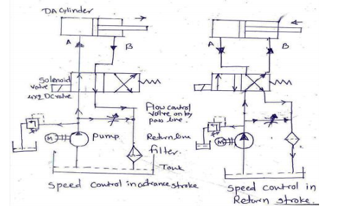
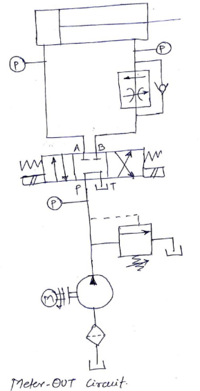
Question:Explain with neat sketch the working of meter out hydraulic circuit.Answer: Meter OUT Circuit A typical meter out circuit is shown in figure. Here the flow control valve is installed in the return line metering the fluid being discharged. In that way, this circuit also gives the control over the actuating speed. But this way of control offers altogether different characteristics to the circuit. Now, the circuit pressure has to overcome the load resistance and the pressure drop across the flow control valve. However, as the flow control valve is on the right side of the piston, the differential area will cause rise in the pressure. This increased pressure helps to overcome the pressure drop across the flow control valve. As the system pressure required will be relatively low, it makes this circuit marginally more efficient on the extend stroke. Initially, the compensatory spool is fully open, and full pump flow is passed into the cylinder until piston moves forward building up pressure at the flow control valve. The compensatory spool will now come into operation and restricts the flow to its correct value. Thus, there is an initial flow surge before the compensatory spool adjusts as in the case of ‘meter-in’ When using meter-out system, the pressure in the rod-end of the cylinder must be carefully considered. With meter-out speed control, the quantity of oil leaving the cylinder is controlled. When the cylinder is extending, the oil from the rod-end is metered which a smaller quantity than that is flowing into the full bore end. Consequently, under extend conditions; meter-out flow control is not as sensitive as meter-in control. When the cylinder is retracting, the reverse is true. Meter-out circuits are best where negative loads may occur, because back pressure is maintained on the exhaust side of the actuator preventing erratic motion. Meter-out circuits provide accurate speed control even with reversing loads. However, as with the meter-in system, considerable heat will be generated when used with a fixed delivery pump and a wide range of piston speeds. Applications: Drilling, Boring, Reaming and tapping operations.
|
| Q 4b)(b) |
6 |
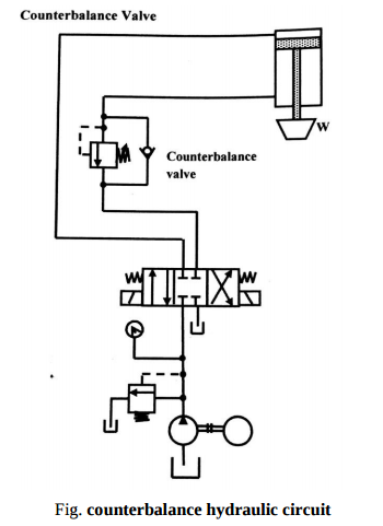
Question:Explain working of counterbalance hydraulic circuit with neat diagram.Answer: Counterbalance valves are commonly used to counterbalance a weight or external force or counteract a weight such as a platen or a press and keep it from freefalling.Figure1.16 illustrates the use of a counterbalance or back-pressure valve to keep a vertically mounted cylinder in the upward position while the pump idles, that is, when the DCV is in its center position. During the downward movement of the cylinder, the counterbalance valve is set to open at slightly above the pressure required to hold the piston up (a check valve does not permit flow in this direction). The control signal for the counterbalance valve can be obtained from the blank end or rod end of the cylinder. If derived from the rod end, the pressure setting of the counterbalance valve equals the ratio of the load to the annulus area of the piston. If derived from the blank end, the pressure setting equals the ratio of load to the area of piston. This pressure is less and hence usually it has to be derived from the blank end. This permits the cylinder to be forced downward when pressure is applied on the top. The check valve is used to lift the cylinder up as the counterbalance valve is closed in this direction. The directional control valve unloads the pump.
|
| Que.No | Marks | |
|---|---|---|
| Q 1a)(iv) |
4 |
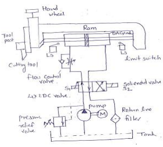
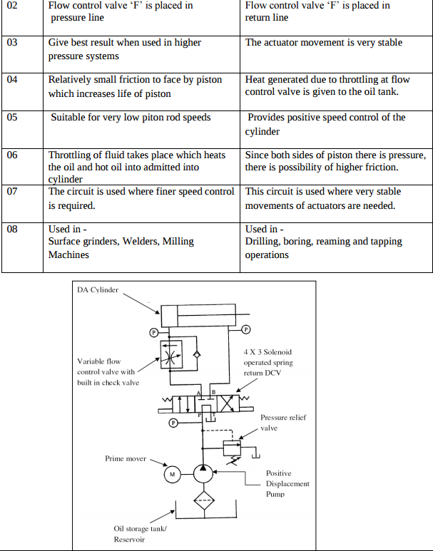
Question:Draw the hydraulic circuit showing control of DA cylinder. Using 4 × 2 DC valve. Explain the working in brief.Answer: Draw the hydraulic circuit showing control of DA cylinder using 4 X 2 DC Valve. Explain the working in brief. Fig shows the circuit used to control DA cylinder using 4 X 2 DC Valve. The operation is described as follows: 1) When the 4/2 way DC valve is in its open center position pump oil flows from port P to port A to the blank end of the cylinder, extending the piston rod against a load. The oil in the rodend of the cylinder is free to flow back to the tank via port B and T. 2) When DC valve is activated then it engaged in cross connection of the ports. The cylinder retracts as the oil flows from ports P and B to the rod end. Oil in the blank end is returned to the tank via ports A and T.
|
| Q 3 c ) |
4 |
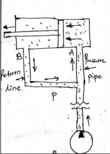
Question:Explain the principle of regenerative circuit.Answer: Principle of regenerative circuit is recovering the energy available with returning oil by using regeneration technique. The concept of re-generative circuit is explained from following figure. Consider the double acting cylinder. Pressurized oil from pump is admitting in cylinder cavity through port (A). Due to pressure force piston is moving from right to left. During this movement, the oil present on piston rod side of piston starts coming out through port (B). This oil will return to the oil reservoir via DC valve. It is clear from figure that, returning oil will enter in pressure pipe through pipe ‘P’ During exit of oil through port (B), some energy is still there with oil on piston rod side. This energy is otherwise wasted if this oil directly goes to oil reservoir. To avoid wastage of this energy, pipe ‘P’ is connected so that, the pressurized oil gets more energy and it will create more pressure force while entering through port (A).
|
| Q 3 e ) |
4 |
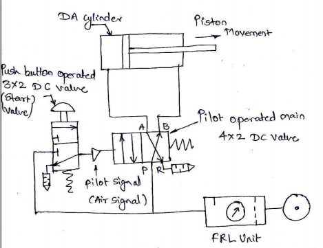
Question:Draw pilot operated DA cylinder circuit using 4 × 2 DC valve and 3 × 2 pilot valveAnswer:
|
| Q 4a)(ii) |
4 |
Question:Draw bleed off circuit and label itAnswer:
|
| Q 5a)(ii) |
8 |
Question:What is impulse circuit? ExplainAnswer: the main valve using the impulse of an impulse valve. As shown in fig. in circuit has two valves ; main valve and impulse valve. Main valve is a single pilot operated spring return type 4/2 direction control valve. Impulse valve is palm button operated spring return type 3/2 direction control valve. In normal position of valves, the double acting cylinder is in retracted position. When the palm button of impulsive valve is pressed manually, compressed air flows to the pilot port of main valve. Hence the speed of main valve will be shifted to the second position. Double acting cylinder is extends.
|
| Q 6 b ) |
4 |
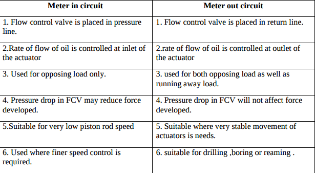
Question:Compare meter in circuit and meter out circuitAnswer:
|
| Q 6 c ) |
4 |
Question:Draw the hydraulic circuit for shaping machine. Explain its workingAnswer:
Parts of shaper machine: Fixed DA cylinder, spool type DC valve, spool shaft stroke adjusting lever, pump, pressure relief valve, return line with filter, oil reservoir. Working: Forward stroke: As shown in fig ,the pump is supplying oil to DA cylinder through DC valve and through port B. Hence piston will move from right to left with force and this is a cutting stroke. Backward Stroke: When lever touches the stopper, then spool shifts to right and flow directions in DC valve change. The oil is entering through port A of DA cylinder and piston will move from left to right. During this stroke, the tool post slightly lift with ideal stroke. ----------------------------------------------------------------------------------------------------- |