Question and answers
| Que.No | Marks | |
|---|---|---|
| Q 1b)(a) |
6 |
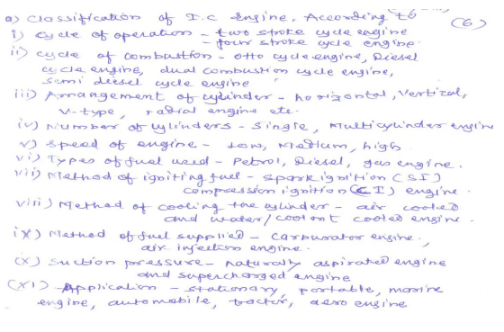
Question:Give classification of IC engines (any six).Answer:
|
| Q 2 a ) |
8 |
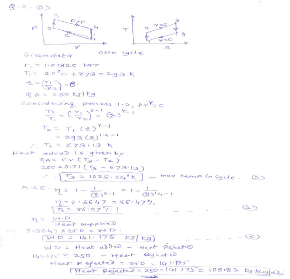
Question:In an Ideal ottocycle the air at the beginning of isentropic compression is at 1.01325 bar and 20°C. The compression ratio is 8. If the heat added during constant volume process is 250 kJ/kg. Determine : a) Maximum temperature in the cycle b) Air standard efficiency c) Work done per cycle d) Heat rejectedAnswer:
|
| Q 3 ) |
4 |
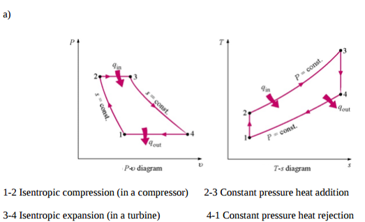
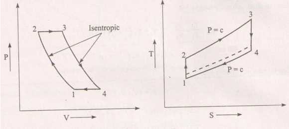
Question:Represent Brayton cycle on PV and TS diagram. Name the processes completing the cycleAnswer:
|
| Q 5 a ) |
8 |
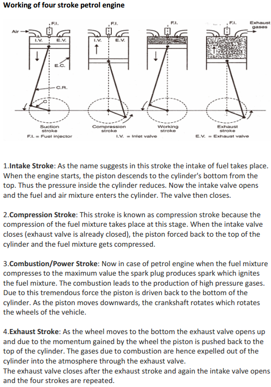
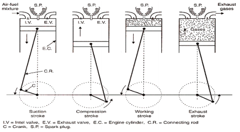
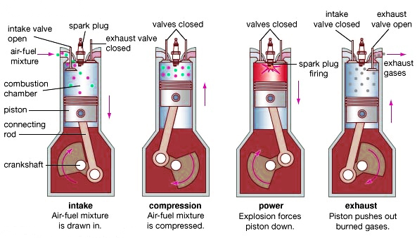
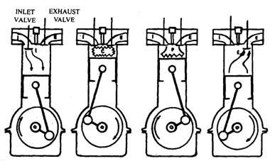
Question:Explain the working of four stroke petrol engine with neat sketch. OR Explain with diagram how the Four stroke petrol engine works.Answer: Four Stroke petrol engine FOUR STROKE PETROL ENGINE refers to its use in petrol engines, gas engines, light, oil engine and heavy oil engines in which the mixture of air fuel are drawn in the engine cylinder. Since ignition in these engines is due to a spark, therefore they are also called spark ignition engines. In four stroke cycle engine, cycle is completed in two revolutions of crank shaft or four strokes of the piston. Each stroke consists of 1800 of crankshaft rotation. Therefore, the cycle consists of 7200 of crankshaft rotation. Cycle consists of following four strokes 1) Suction Stroke 2) Compression Stroke 3) Expansion or Power Stroke 4) Exhaust Stroke SUCTION STROKE: In this Stroke the inlet valve opens and proportionate fuel-air mixture is sucked in the engine cylinder. Thus the piston moves from top dead centre (T.D.C.) to bottom dead centre (B.D.C.). The exhaust valve remains closed through out the stroke. COMPRESSION STROKE: In this stroke both the inlet and exhaust valves remain closed during the stroke. The piston moves towards (T.D.C.) and compresses then closed fuel-air mixture drawn. Just before the end of this stroke the operating. plug initiates a spark which ignites the mixture and combustion takes place at constant pressure.
4 stroke petrol engine animation
POWER STROKE OR EXPANSION STROKE: In this stroke both the valves remain closed during the start of this stroke but when the piston just reaches the B.D.C .the exhaust valve opens. When the mixture is ignited by the spark plug the hot gases are produced which drive or throw the piston from T.D.C. to B.D.C. and thus the work is obtained in this stroke. EXHAUST STROKE: This is the last stroke of the cycle. Here the gases from which the work has been collected become useless after the completion of the expansion stroke and are made to escape through exhaust valve to the atmosphere. This removal of gas is accomplished during this stroke. The piston moves from B.D.C. to T.D.C. and the exhaust gases are driven out of the engine cylinder; this is also called scavenging A multi cylinder Four stroke petrol engine looks like this.
Links to other pages of power engineering ----------------------------------------------------------------------------------------------------- |

| Que.No | Marks | |
|---|---|---|
| Q 1a)(a) |
4 |
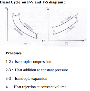
Question:Draw p-v and T-S diagram for Diesel cycle. Name the processes involved in it.Answer: Diesel Cycle on P-V and T-S diagram :
Processes : 1-2 : Isentropic compression 2-3 : Heat addition at constant pressure 3-3 Isentropic expansion 4-1 Heat rejection at constant volume ----------------------------------------------------------------------------------------------------- |
| Q 1a)(b) |
4 |
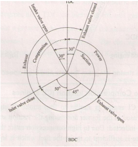
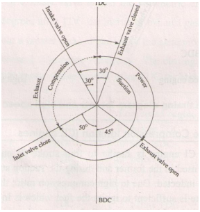
Question:Draw actual valve timing diagram for 4-stroke petrol engine.Answer: Valve timing diagram of four stroke diesel engine
|
| Q 1b)(a) |
6 |
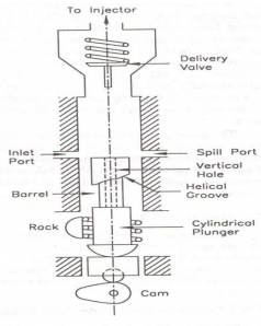
Question:Draw a neat labelled sketch of fuel injection pump. Give its function.Answer: Fuel injection pump : Fuel injection pump is used widely for the supply of fuel under high pressure in diesel engines
|
| Q 3 a ) |
4 |
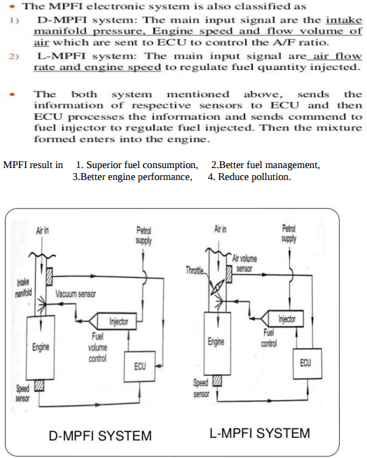
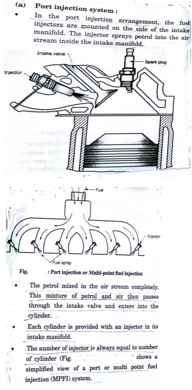
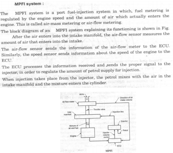
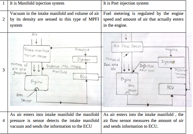
Question:Explain MPFI with neat sketch.Answer: Attempt any FOUR MPFI : MPFI means Multipoint Injection System in which each cylinder has number of injector to supply / spray the fuel in cylinders.
|
| Q 3 b ) |
4 |
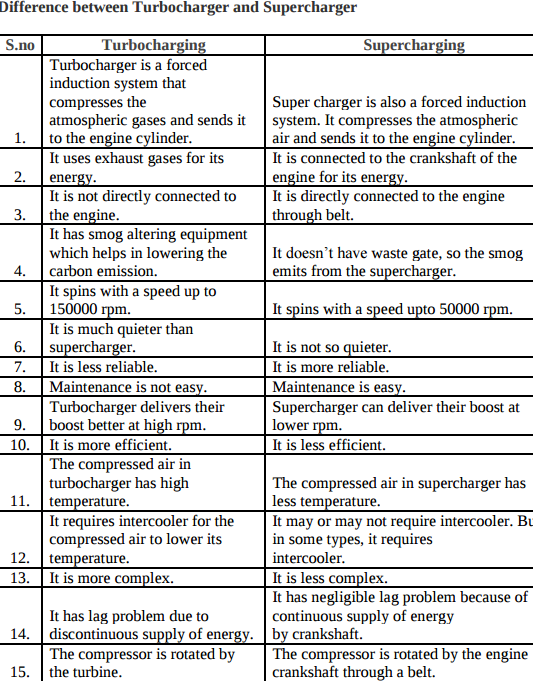
Question:Differentiate supercharging and turbocharging in I.C. engine.Answer:
|
| Q 4a)(d) |
4 |
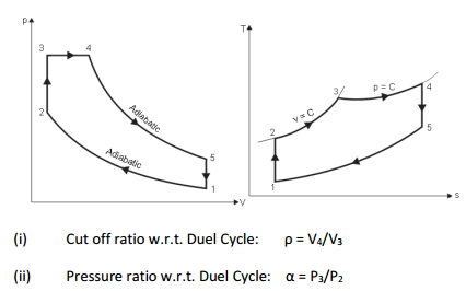
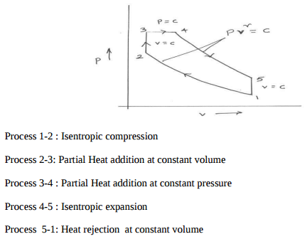
Question:Explain w.r.to. dual cycle i) cutoff ratio ii) pressure ratio.Answer: Duel cycle:
|
| Q 4b)(b) |
6 |
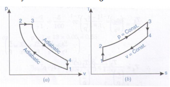
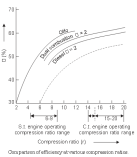
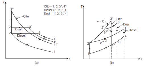
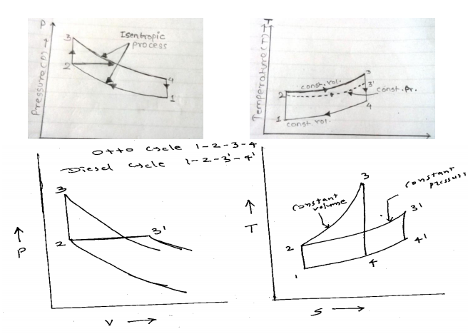
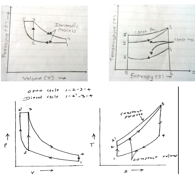
Question:Draw superimposed p-v diagram of Otto cycle, Diesel cycle and Dual cycle to compare their efficiencies for same compression ratio (R c ) and heat rejection (Q r ).Answer: Superimposed P-V Diagram of Otto, Diesel & Duel Cycle: A comparison of the cycles (Otto, Diesel and Dual) on the p-v and T-s diagrams for the same compression ratio and heat supplied is shown in the Fig. Since all the cycles reject their heat at the same specific volume, process line from state 4 to 1, the quantity of heat rejected from each cycle is represented by the appropriate area under the line 4 to 1 on the T-s diagram. As is evident from the cycle which has the least heat rejected will have the highest efficiency. Thus, Otto cycle is the most efficient and Diesel cycle is the least efficient of the three cycles
|
| Que.No | Marks | |
|---|---|---|
| Q 1a)(a) |
4 |
Question:Represent ‘Brayton Cycle’ on P-V and T-S diagram.Answer:
|
| Q 1a)(d) |
4 |
Question:Draw ‘Valve timing diagram for 4-stroke cycle diesel engine.Answer:
|
| Q 3 d ) |
4 |
Question:What is ‘Scavenging’ ? List any two types of ‘scavenging’.Answer: Scavenging: At the end of expansion stroke the combustion chambers of a two stroke engine is left full of products of combustion. This is because unlike four stroke engines, there is no exhaust stroke available to clear the cylinder of burnt gases in two stroke engine the process of clearing the cylinder after the expansion stroke is called scavenging process. The scavenging systems are as follows : 1. Uniform scavenging system 2. Cross scavenging system 3. Loop or reverse scavenging system ----------------------------------------------------------------------------------------------------- |
| Q 3 e ) |
4 |
Question:Explain in brief the importance of ‘Super Charging’.Answer: Supercharging: The power output of an engine depends upon the amount of air inducted in cylinder per unit time, the degree of utilization of this air and the thermal efficiency of the engine. The amount of air inducted per unit time can be increased by increasing the engine speed or by increasing the density of air at intake. As engine speed increases, the inertia load, engine friction, bearing load increases. The method of increasing the inlet air density is called as supercharging. It is usually employed to increase the power output of the engine. The increase of the amount of air inducted per unit time by supercharging is obtained mainly to burn greater amount of fuel in a given engine. Supercharging increases the power output for a given weight and bulk of engine, compensate for loss of power due to altitude and obtain more power from the existing engine ----------------------------------------------------------------------------------------------------- |
| Q 4a)(a) |
4 |
Question:Explain in brief the constructional features of MPFI engineAnswer: Absence of Venturi – No Restriction in Air Flow/Higher Vol. Eff./Torque/Power • Hot Spots for Preheating cold air eliminated / Denser air enters • Manifold Branch Pipes not concerned with Mixture Preparation • Better Acceleration Response • Fuel Atomization Generally Improved. • Use of Greater Valve Overlap • Use of Sensors to Monitor Operating Parameters/Gives Accurate Matching of Air/fuel Requirements: Improves Power, Reduces fuel consumption and Emissions • Precise in Metering Fuel in Ports • Precise Fuel Distribution Between Cylinders • Fuel Transportation in Manifold not required so no Wall Wetting • Fuel Surge During Fast Cornering or Heavy Braking Eliminated • Adaptable and Suitable For Supercharging • Increased power and torque. ----------------------------------------------------------------------------------------------------- |
| Q 4a)(c) |
4 |
Question:State any four effect of detonationAnswer: Effects of detonation (1) Noise – As intensity of detonation increases, the sound intensity increases & it is harmful. (2) Mechanical damage – shock waves are so violent that it may cause mechanical damage like breaking of piston. It increases the rate of wear erosion of piston. (3) Pre-ignition – Due to local overheating of spark plug & this pre-ignition increases detonation. (4) Power output & efficiency decreases - Power output & thermal efficiency decreases due to abnormal combustion. (5) Increase in heat transfer – Temperature of cylinder in detonating engine is higher than in non – detonating engine, hence increases the heat transfer. (6) Carbon deposits- Detonation results in increased carbon deposits. ----------------------------------------------------------------------------------------------------- |
| Q 4b)(b) |
6 |
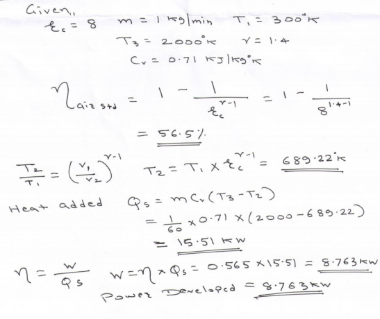
Question:A petrol engine working on constant volume cycle has compression ratio of 8 and consume 1 kg of air per minute, if minimum and maximum temp. during cycle is 300 °K and 2000 °K respectively. Find power developed by engine. Assume γ = 1.4 and Cv = 0.71 kJ/kg °K.Answer:
|
| Q 6 c ) |
4 |
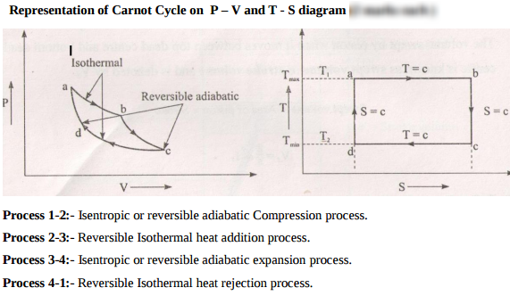
Question:Represent Carnot cycle on P-V and T-S diagramAnswer:
|
| Que.No | Marks | |
|---|---|---|
| Q 1a)(a) |
4 |
Question:State four assumptions made for air standard cycle.Answer: Assumption made in air standard cycle Following assumption made in actual cycle to analysis as air standard cycle. 1. The working fluid is perfect gas. 2. There is no change in mass of the working medium. 3. All the process that constitutes the cycle is reversible. 4. Heat is assumed to be supplied from a constant high temperature source and not from chemical reaction during the cycle. 5. There are no heat losses. 6. The working medium has constant specific heats throughout the cycle. ----------------------------------------------------------------------------------------------------- |
| Q 1a)(c) |
4 |
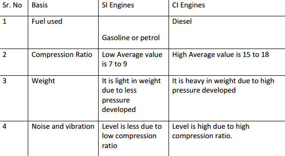
Question:Compare SI and CI engine on the basis of i) fuel used, ii) Compression ratio, iii) Weight, iv) Noise and vibrationAnswer: Difference between SI and CI engines
|
| Q 3 d ) |
4 |
Question:Name four sensors used in I.C. engine and explain working of any one.Answer: Sensor used in IC engines ( Explanation of any one ) A sensor is an input device that provides variable information on an engine function. Examples of sensors include the airflow sensor (AFS), crank angle sensor (CAS), throttle potentiometer sensor (TPS) etc, and these provide data on load, rpm, temperature, throttle opening etc. This data is signaled to the ECM, which then analyses the results and computes an output signal. The output signal is used to actuate an n output device. Crank angle sensor: A permanent magnet inductive signal generator is mounted in close proximity to the flywheel, where it radiates a magnetic field. As the flywheel spins and the pins are rotated in the magnetic field, an alternating (AC) waveform is delivered to the ECM to indicate speed of rotation. If a pin is intentionally omitted at two points on the flywheel, or by contrast a double pin is used, the signal will vary at these points, and a reference to TDC will be returned to the ECM. The location of the positional signal is not at TDC, but may be some other point fixed by the VM. When used, the CAS provides the primary signal to initiate both ignition and fuelling. Air Flow Sensor (AFS): The AFS is normally located between the air filter and the throttle body. As air flows through the sensor, it deflects a vane (flap) which wipes a potentiometer resistance track and so varies the resistance of the track and generates a variable voltage signal. Manifold absolute pressure (MAP) sensor: The MAP sensor measures the manifold vacuum or pressure, and uses a transducer to convert the signal to an electrical signal which is returned to the ECM. The unit may be designed as an independent sensor that is located in the engine compartment or integral with the ECM. Coolant temperature sensor (CTS): The CTS is a two-wire thermistor that measures the coolant temperature. The CTS is immersed in the engine coolant, and contains a variable resistor that usually operates on the NTC principle. Throttle Position Sensor (TPS): TPS is provided to inform the ECM of idle position, deceleration, rate of acceleration and wide-open throttle (WOT) conditions. The TPS is a potentiometer which varies the resistance and voltage of the signal returned to the ECM. 01 03 MAHARASHTRA STATE BOARD OF TECH From the voltage returned, the ECM is able to calculate idle position, full-load and also how quickly the throttle is opened. Oxygen sensor (OS): An oxygen sensor is a ceramic device 'placed in the exhaust manifold on the engine side of the catalytic converter. The oxygen sensor returns a signal to the ECM, which can almost instantaneously (within 50 ms) adjust the injection duration. ----------------------------------------------------------------------------------------------------- |
| Q 3 e ) |
4 |
Question:What is scavenging in I.C. engine ? State its types.Answer: Scavenging : In two stroke engines , at the end of expansion stroke, combustion chamber is full of products of combustion. This is due to elimination of exhaust stroke like in four stroke engine. Scavenging is the process of clearing the cylinder after the expansion stroke. This is done short duration of time available between end of expansion and start of charging process. Types of scavenging : 1. Uniflow scavenging process 2. Cross scavenging process 3. Loop or reverse scavenging process ----------------------------------------------------------------------------------------------------- |
| Q 4a)(a) |
4 |
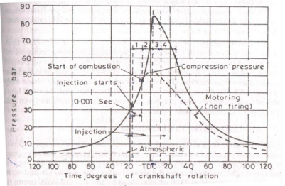
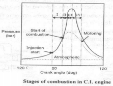
Question:Explain the process of combustion in diesel engine.Answer: Combustion in CI Engines :The combustion in CI engines is taking place in following stages as shown in figure 1. Ignition delay period: During this period, some fuel has been admitted but not yet ignited. The delay period is a sort of preparatory phase. It is counted from the start of injection to the point where P-ɵ curve separates from air compression curve. 2. Rapid or uncontrolled combustion : In this stage , the pressure rises rapid because during the delay period the fuel droplets have time to spray and have fresh air around them. This period is counted from end of delay period to the max pressure on indicator diagram. 3. Controlled combustion : uncontrolled combustion is followd by controlled combustion stage. The period of this stage assumed to be at the end of max cycle temperature. 4. After burning : It is expected to end combustion process after third stage. Because of poor distribution of fuel particles combustion still continues during remaining part of expansion stroke. This is after burning .
|
| Q 4a)(b) |
4 |
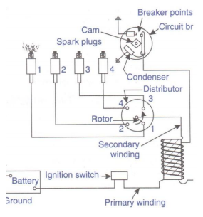
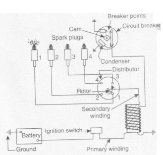
Question:Explain battery ignition in S.I. engine.Answer: Battery Ignition system : It consists of a battery of 6 or 12 volts, ignition switch, induction coil, condenser, distributor and a circuit breaker. One terminal of battery is ground to the frame of the engine and other is connected through the ignition switch to one primary terminal of the ignition coil . The other terminal is connected to one end of contact points of the circuit breaker. To start with the ignition switch is made on and the engine is cranked. The contacts touch, the current flows from battery through the switch. A condenser connected across the terminals of the contact breaker points prevent the sparking at these points. The rotating cam breaks open the contacts immediately and breaking of this primary circuit brings about a change in the magnetic fields and voltage changes from 12 to 12000 V. due to the high voltage. The spark jumps across the gap in the spark plug and air fuel mixture is ignited in the cylinder
|
| Q 6 b ) |
4 |
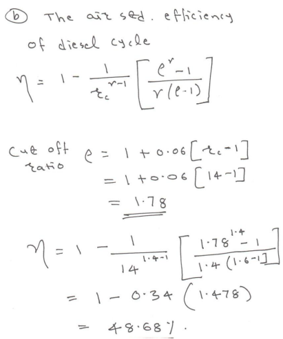
Question:A diesel engine has a compression ratio of 14 and cut-off takes place at 6% of stroke. Find the air standard efficiency.Answer:
|
| Que.No | Marks | |
|---|---|---|
| Q 1a)(a) |
4 |
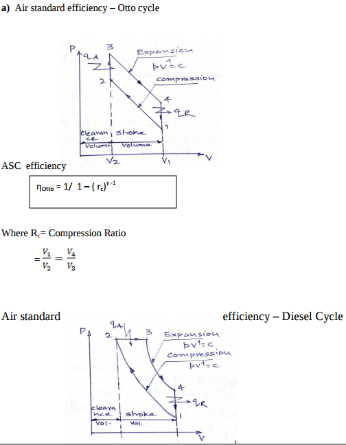
Question:Write the equations for air standard efficiency of otto cycle and diesel cycle and state various terms involved in it.Answer:
|
| Q 3 a ) |
4 |
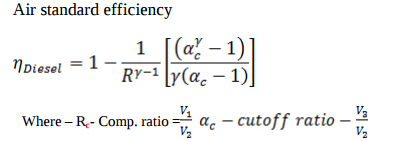
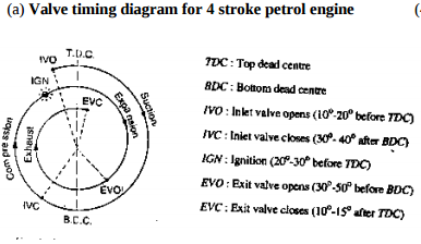
Question:Draw actual valve timing diagram for 4-stroke petrol engine.Answer:
|
| Q 3 b ) |
4 |
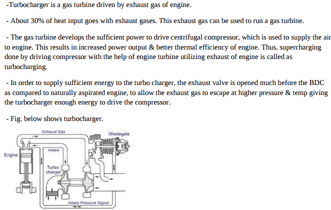
Question:Explain turb charging with a neat sketch.Answer:
|
| Q 4 a ) |
4 |
Question:What are the causes of detonation in I.C. engine ?Answer: The loud pulsating noise heard within the engine cylinder is known as detonation. The following are the certain factors which causes detonation. (1) The shape of the combustion chamber. (2) The relative position of the sparking plugs in case of petrol engines. (3) The chemical nature of the fuel. (4) The initial temp & pressure of fuel (5) The rate of combustion of that portion of fuel which is the first to ignite. This portion of fuel in heating up , compresses the remaining unburnt fuel, thus producing the condition for auto ignition to occur. ----------------------------------------------------------------------------------------------------- |
| Q 4b)(a) |
6 |
Question:Explain with neat sketch turning moment diagram for a four-stroke engine.Answer:
|
| Q 6 a ) |
4 |
Question:What is MPFI ? Explain any one MPFI system with neat sketch.Answer: The MPFI means multi point injection system. In this system each cylinder has number of injector to supply/ spray fuel in cylinder as compared to one injector located centrally to supply and spray fuel in case of single point injection system
----------------------------------------------------------------------------------------------------- |
| Que.No | Marks | |
|---|---|---|
| Q 1a)(a) |
4 |
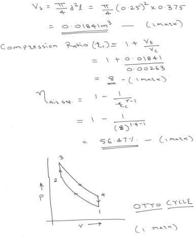
Question:An engine of diameter 250 mm and 375 mm stroke works on otto cycle. The clearance volume is 0.00263 m3, find the air standard efficiency of cycle also sketch the cycle on P-V plane.Answer:
|
| Q 1a)(d) |
4 |
Question:What is pre-ignition ? State any two factors responsible for pre-ignition.Answer: In S.I. engine, the spark is timed to occur at a definite point just before the end of the compression stroke. If the ignition starts, due to any other reason, when the piston is still doing its compression stroke, it is known as pre – ignition. Following factors are responsible for Pre – ignition 1) High compression ratio 2) Overheated spark plug 3) Incandescent carbon deposit in cylinder wall 4) Overheated exhaust valve 5) It may occur due to faulty timing of spark production ----------------------------------------------------------------------------------------------------- |
| Q 1b)(a) |
6 |
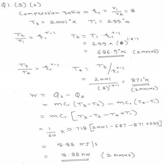
Question:A petrol engine working on otto cycle has compression ratio 8 and consumes 1 kg of air per minute. If maximum temperature during the cycle is 2001 k and minimum temperature is 299 k. Find power developed by engine.Answer:
|
| Q 3 d ) |
4 |
Question:Name the different sensors used in ECU of modern automobile with their application. (minimum 4Answer: Crank angle sensor: A permanent magnet inductive signal generator is mounted in close proximity to the flywheel, where it radiates a magnetic field. As the flywheel spins and the pins are rotated in the magnetic field, an alternating (AC) waveform is delivered to the ECM to indicate speed of rotation. Air Flow Sensor (AFS): The AFS is normally located between the air filter and the throttle body. As air flows through the sensor, it deflects a vane (flap) which wipes a potentiometer resistance track and so varies the resistance of the track and generates a variable voltage signal. Manifold absolute pressure (MAP) sensor: The MAP sensor measures the manifold vacuum or pressure, and uses a transducer to convert the signal to an electrical signal which is returned to the ECM. The unit may be designed as an independent sensor that is located in the engine compartment or integral with the ECM. Coolant temperature sensor (CTS): The CTS is a two-wire thermistor that measures the coolant temperature. The CTS is immersed in the engine coolant, and contains a variable resistor that usually operates on the NTC principle. Throttle Position Sensor (TPS): TPS is provided to inform the ECM of idle position, deceleration, rate of acceleration and wide-open throttle (WOT) conditions. The TPS is a potentiometer which varies the resistance and voltage of the signal returned to the ECM. Oxygen sensor (OS): An oxygen sensor is a ceramic device 'placed in the exhaust manifold on the engine side of the catalytic converter. The oxygen sensor returns a signal to the ECM, which can almost instantaneously (within 50 ms) adjust the injection duration. ----------------------------------------------------------------------------------------------------- |
| Q 3 e ) |
4 |
Question:Explain different stages of combustion in C.I. engine with sketch.Answer: 1) Ignition delay period : During this fuel has already admitted but has not yer ignited. This is counted from start of injection to the point where P-O curve separates from pure air compression curve. 2) Rapid or uncontrolled combustion : In this stage pressure rise because of during the delay period the fuel droplet have time to spread over a wide area and fresh air around them. 3) Controlled combustion : The temperature and pressure rise in the second state is quite high, hence droplet of fuel injected in stage burn faster with reduced ignition delay as soon as they find necessary oxygen and further pressure rise is controlled by injection rate. 4) After burning : This sage may not be present in all cases. Because of poor distribution of fuel particles, combustion continues during part of the remainder of the expansion stroke.
|
| Q 4a)(a) |
4 |
Question:Explain MPFI system with sketchAnswer:
|
| Q 4a)(c) |
4 |
Question:Draw and explain Battery ignition system.Answer: Battery Ignition system : I t consists of six or twelve volt battery, ignition switch,induction coil, circuit breaker condenser and distributor. All the circuit parts are shown in figure. One terminal of battery is ground to engine frame and other is connected through the ignition switch to one primary terminal of induction coil. The other primary connection is connected to one end of contact point of circuit breaker and through closed points to ground. The ignition switchis made on and engine is crancked. When the contacts touch, the current flows the battery to the switch. Due to this primary winding of induction coil to circuit breaker points and circuit is completed. A condenser prevents sparking of this point. The rotating cam breaks open the contacts immediately and breaking of this primary circuit brings about change of magnetic field causing very high volt about 8000 to 12000 volts. Due to this high voltage the spark jumps across the gap in the spark plug and thereby it ignites mixture of air and fuel.
|
| Q 4b)(b) |
6 |
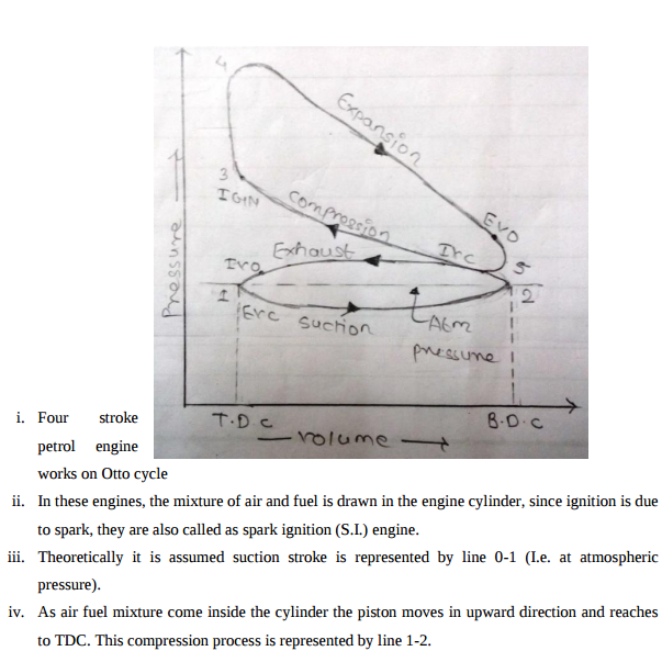
Question:Explain working of 4 stroke S.I. engine with neat sketch. or With neat sketches explain the working principle of four stroke spark ignition engine.Answer: Four stroke spark ignition engine working principle
Four stroke spark ignition engine working principle.Four stroke spark ignition engine is given below in 4 steps, 1. Suction stroke: Suction stroke starts when piston is at top dead center and about to move downwards. During suction stroke inlet valve is open and exhaust valve is closed. Due to low pressure created by the motion of the piston towards bottom dead center, the charge consisting of fresh air mixed with the fuel is drawn into cylinder. At the end of suction stroke the inlet valve closes. 2. Compression stroke: During compression stroke, the compression of charge takes place by return stroke of piston, i.e. when piston moves from BDC to TDC. During this stroke both, inlet and exhaust valve remain closed. Charge which is occupied by the whole cylinder volume is compressed up to the clearance volume. Just before completion of compression stroke, a spark is produced by the spark plug and fuel is ignited. Combustion takes place when the piston is almost at TDC. 3. Expansion or power stroke: Piston gets downward thrust by explosion of charge. Due to high pressure of burnt gases, piston moves downwards to the BDC. During expansion stroke both inlet and exhaust valves remains closed. Thus power is obtained by expansion of products of combustion. Therefore it is also called as ‘power stroke’. Both pressure as well as temperature decreases during expansion stroke. 4. Exhaust stroke: At the end of expansion stroke the exhaust valve opens, the inlet valve remains closed and the piston moves from BDC to TDC. During exhaust stroke the burnt gases inside the cylinder are expelled out. The exhaust valve closes at the end of the exhaust stroke but still some residual gases remains in cylinder. ======================Answer ends here================== Additional information about Four stroke spark ignition engine for better understanding
----------------------------------------------------------------------------------------------------- |
| Q 6 c ) |
4 |
Question:Draw P-V and T-S diagram for dual cycle. Name the processes involved in it.Answer:
|
| Que.No | Marks | |
|---|---|---|
| Q 1a)(i) |
4 |
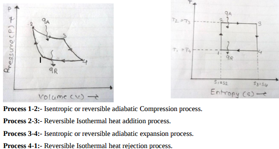
Question:Why does the Carnot heat engine not exist in practice? Give any four pointsAnswer: Carnot heat engine is an ideal heat engine and is not possible in practice due to following reasons. i) Alternate adiabatic and isothermal process is not possible. ii) Heat addition and heat rejection at constant temperature is not possible. iii) All processes are reversible which is not possible in practice ----------------------------------------------------------------------------------------------------- |
| Q 1a)(iv) |
4 |
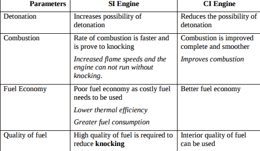
Question:Compare the effect of supercharging on S.I. engine and C.I. engine with respect to following parameters: 1) detonation 2) combustion 3) fuel economy 4) quality of fuel.Answer: Effect of Supercharging on SI and CI engine
|
| Q 3 d ) |
4 |
Question:Draw super imposed PV and TS diagrams of otto cycle, diesel cycle and dual cycle to compare their efficiencies under the following conditions: (i) for same compression ratio and heat rejection (ii) for same maximum pressure and temperature and heat rejection.Answer: Same compression ratio and same heat rejected heat rejection
ii) For same maximum pressure and temperature and heat rejection
|
| Q 3 e ) |
4 |
Question:Draw P-V and T-S diagram for carnot cycle. Name the processes involved in it.Answer: PV and TS diagram of Carnot cycle
|
| Q 4a)(ii) |
4 |
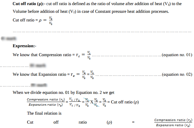
Question:Define cut off ratio. Express it in terms of compression ratio and expansion ratio.Answer:
|
| Q 4a)(iii) |
4 |
Question:Differentiate between L-MPFI system and D-MPFI system.Answer:
|
| Q 4a)(l) |
4 |
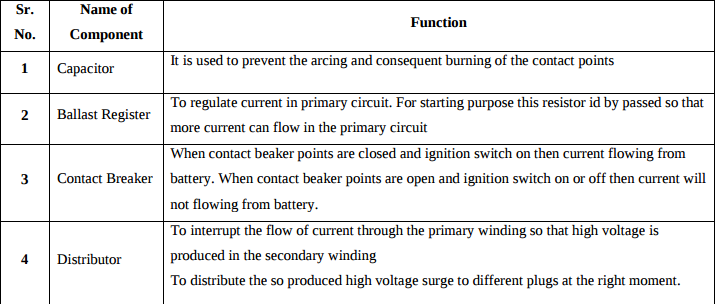
Question:State the functions of following components used in battery ignition system: 1) capacitor 2) ballast register 3) contact breaker 4) distributorAnswer: Function of Components used in battery ignition system
|
| Q 4b)(ii) |
6 |
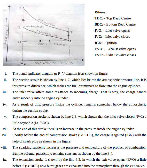
Question:Draw theoretical and actual P-V diagrams for S.I. engines and explain brieflyAnswer:
v. When piston is at TDC the air fuel mixture is come in clearance volume and theoretically it is assumed that spark is ignited in cylinder when piston is at TDC and volume during this combustion is constant (i.e. clearance volume) vi. At the end of combustion burnt gases exert pressure on piston and pushes the piston in downward direction. This process is represented by line 3-4, this process is also called as exhaust stroke. vii. At the end of this stroke exhaust valve is open and this burnt gases are expel out to atmosphere. viii. This exhaust stroke is represented by line 1-0 at atmospheric pressure.
x. The exhaust stroke is shown by the line 5-1, which lies above the atmosphere pressure line. It is pressure difference, which makes the burnt gases to flow out the engine cylinder. xi. The exit valve offers some resistance to the outgoing burnt gases. That is why, the burnt gases cannot escape suddenly from the atmospheric pressure line during the exhaust stroke. ----------------------------------------------------------------------------------------------------- |
| Q 6 a ) |
4 |
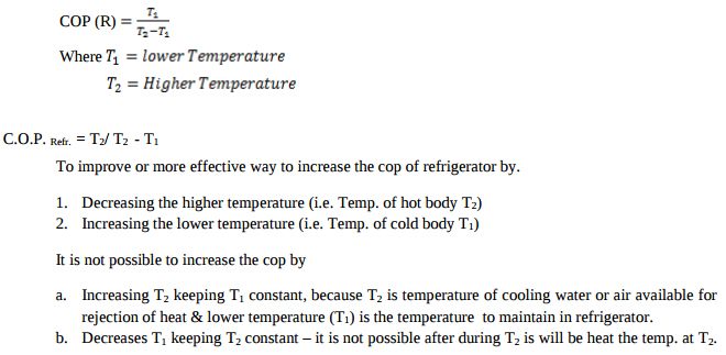
Question:Which is more effective way to increse the C.O.P. of refrigerator, to increase T2 keeping T1 constant or to decrease T1 keeping T2 constant? (T1 > T2). Give justification to your answer.Answer:
|
| Q 6 c ) |
4 |
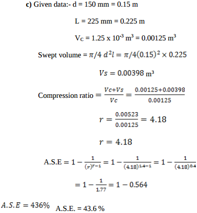
Question:An engine working on otto cycle has, d = 150 mm, L = 225 mm υc = 1.25 × 10⁻³ m3. Find air standard efficiency.Answer:
|
| Q 6 e ) |
4 |
Question:In gas turbine plants, Brayton cycle is more suitable than otto cycle, even though both cycles have equal thermal efficiency for same compression ratio. JustifyAnswer: In gas turbine plant – it works on brayton cycle where the heat added & heat rejected at constant pressure. It consists of compressor, combustion chamber & a turbine. The efficiency of Brayton cycle rotor cycle is same for but efficiency is of gas it temperature & pressure is increasing. High temperature & pressure require for ignition & fuel consumption for bray ton cycle. It is not possible in Oto cycle because the heat added & rejected at constant volume so bray ton cycle is most suitable than Otto cycle for gas turbine plant. ----------------------------------------------------------------------------------------------------- |
| Que.No | Marks | |
|---|---|---|
| Q 1a)(a) |
4 |
Question:Draw P-V and T-S diagram for Diesel cycle. Name the processes involved in it.Answer:
|
| Q 3 a ) |
4 |
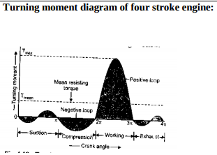
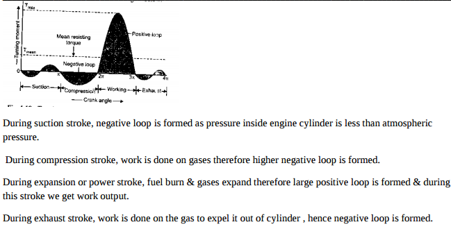
Question:Draw turning moment diagram for four stroke petrol engine and explain it in brief.Answer:
During suction stroke, negative loop is formed as pressure inside engine cylinder is less than atmospheric pressure. During compression stroke, work is done on gases therefore higher negative loop is formed. During expansion or power stroke, fuel burn & gases expand therefore large positive loop is formed & during this stroke we get work output. During exhaust stroke, work is done on the gas to expel it out of cylinder, hence negative loop is formed. ----------------------------------------------------------------------------------------------------- |
| Q 3 b ) |
4 |
Question:What is supercharging ? State advantages of supercharging.Answer: Superchargers are pressure boosting devices (compressors) which increase the pressure of the air before inletting it get into cylinder of the internal combustion engine, and the process of increasing the pressure OR forcing more air to get into engine is called as supercharging. This gives each intake cycle of the engine more oxygen, letting it burn more fuel and do more work, thus increasing power. Advantages 1. Higher power output. 2. Reduced smoke from exhaust gases. The extra air pushed into cylinder, helps the air to complete combust leading to lesser smoke generation. 3. Quicker acceleration of vehicle. Supercharger starts working as soon as the engine starts running. This way the engine gets a boost even at the beginning leading to quicker acceleration. 4. Cheaper than turbocharger. ----------------------------------------------------------------------------------------------------- |
| Q 4a)(a) |
4 |
Question:What are the effects of detonation in I.C. engine ?Answer: Effects of detonation (1) Noise – As intensity of detonation increases, the sound intensity increases & it is harmful. (2) Mechanical damage – shock waves are so violent that it may cause mechanical damage like breaking of piston. It increases the rate of wear erosion of piston. (3) Pre-ignition – Due to local overheating of spark plug & this pre-ignition increases detonation. (4) Power output & efficiency decreases - Power output & thermal efficiency decreases due to abnormal combustion. (5) Increase in heat transfer – Temperature of cylinder in detonating engine is higher than in non – detonating engine, hence increases the heat transfer. (6) Carbon deposits- Detonation results in increased carbon deposits ----------------------------------------------------------------------------------------------------- |
| Q 4b)(a) |
6 |
Question:Explain with neat sketch working principle of four stroke petrol engine.Answer:
|