Draw and explain pneumatic meter in circuit to control of speed extension.
.Draw and Explain pneumatic meter in circuit to control of speed extension. In meter in pneumatic circuit flow control valve with check valve is fitted between DCV and actuator. For speed control of actuator during extension stroke, FCV with check valve is fitted on piston side of the actuator as shown in figure. With a meter-in circuit, fluid enters into the actuator at a controlled rate. Pneumatic circuit diagram for meter-in flow-control circuit is as shown in figure. In this circuits, the rate of flow of compressed air into the cylinder is controlled by flow control
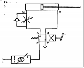
valve. FCV is placed at inlet of the cylinder. Cap end port “C” is inlet for extension and rod end port “R” is inlet for retraction. Working: In first position of 4/2 DCV, compressed air flows from P to A and B to T. this flow is through flow control valve, the flow is controlled and hence piston extends slowly. In second position 4/2 DCV, compressed air flows P to B and A to T. this flow is through check valve. This is free flow. Hence the piston retracts at higher speed, Which is not controlled.