Draw a general layout of pneumatic system and state the function of components
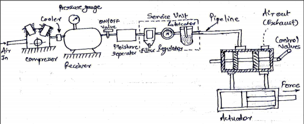
1) Air inlet filter – Free air from the atmosphere enters the compressor through an air-inlet filter which will essentially keep out the dust and dirt from entering the system. 2) Compressor: It is used to compress the air from atmosphere pressure to the desired higher pressure level. It can be single stage or multistage in operation. 3) Cooler: Removes the heat generated during the process of operation. 4) Pressure switch and control unit: Maintains the pressure in the receiver in the predetermined range by starting and stopping the prime mover. 5) Moisture separator: Cooling air in the cooler results in condensation of vapor in the air. The condensate in the form of water droplets are separated from air. 6) Service unit: Filter – Separates sub-micron level contamination. Regulator – Bring the pressure of air from receiver pressure to the device pressure. Lubricator – Adds lubricants to air. 7) Pipe Line: They carry the compressed air from one location to another. 8) Control Valves: They are required to control the air direction, pressure and flow rate. They are responsible for the smooth and precise control of the pneumatic actuator, and also for the safe operation of the system. 9) Actuator: They will convert the high pressure energy of the compressed air into mechanical force or do useful work. Actuators can either be pneumatic cylinders to provide linear motion or pneumatic motors to provide rotary motion.