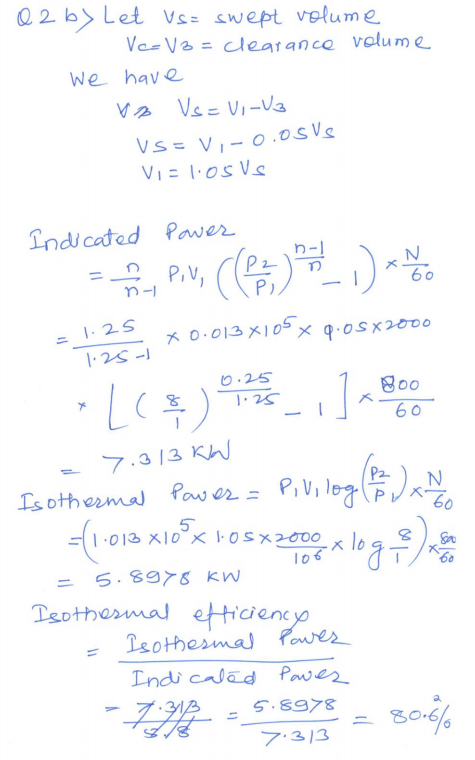
A single stage reciprocating air compressor has a swept volume of 2000 cm3 and runs at 800 rpm.
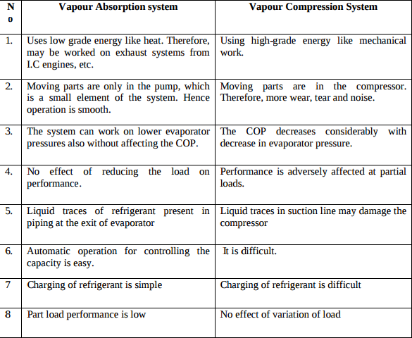
Differences between Vapour Absorption and Vapour Compression refrigeration system
Non dispersive infra red gas analyzer ( NDIR) : The working principle of infra red gas exhaust gas analyzer is as shown in figure . It works on the principle of hetero atomic gases absorbs infra red energy at distinct and separated wavelength. The absorbed energy raises the temperature and pressure of confined gas. This enables to measure contents of hydro carbon and carbon monoxide. This is a faster method of gas analysis. The standard sample is filled in reference cell R . the sample of gas under testing is filled in cell S .
Lobe type air compressor: it is a rotary type of compressor consisting of two rotors which are driven externally. One rotor is connected to drive and second is connected to gear. These two rotors have two or three lobes having epicycloids, hypocycloid or involutes profiles. In the figure two lobes compressor is shown with a inlet arrangement and receiver. A very small clearance is maintained between surfaces so that wear is prevented. Air leakage through this clearance decreases efficiency of this compressor.
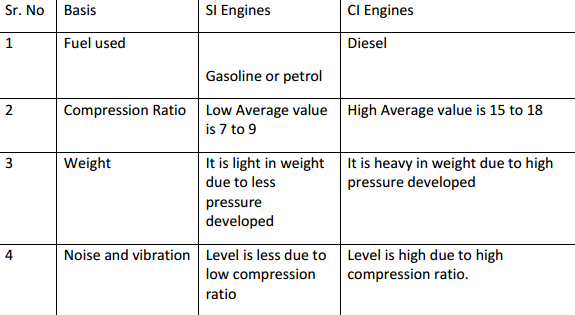
Difference between SI and CI engines
Assumption made in air standard cycle Following assumption made in actual cycle to analysis as air standard cycle. 1. The working fluid is perfect gas. 2. There is no change in mass of the working medium. 3. All the process that constitutes the cycle is reversible. 4. Heat is assumed to be supplied from a constant high temperature source and not from chemical reaction during the cycle. 5. There are no heat losses. 6. The working medium has constant specific heats throughout the cycle.
Speed control of any actuator (Cylinders or motors) can be controlled using flow control valves. Varying the rate of flow of oil will vary the speed of the actuator.(Explanation 1Mark) In meter in circuit, rate of flow of oil is controlled at inlet of the actuator. In meter out circuit, rate of flow of oil is controlled at outlet of the actuator. In bleed off circuit, rate of flow of oil is controlled in the by-pass line leading towards the tank.