Explain working of counterbalance hydraulic circuit with neat diagram.
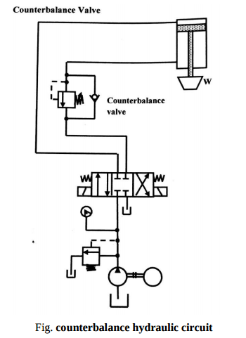
Counterbalance valves are commonly used to counterbalance a weight or external force or counteract a weight such as a platen or a press and keep it from freefalling.Figure1.16 illustrates the use of a counterbalance or back-pressure valve to keep a vertically mounted cylinder in the upward position while the pump idles, that is, when the DCV is in its center position. During the downward movement of the cylinder, the counterbalance valve is set to open at slightly above the pressure required to hold the piston up (a check valve does not permit flow in this direction). The control signal for the counterbalance valve can be obtained from the blank end or rod end of the cylinder. If derived from the rod end, the pressure setting of the counterbalance valve equals the ratio of the load to the annulus area of the piston. If derived from the blank end, the pressure setting equals the ratio of load to the area of piston. This pressure is less and hence usually it has to be derived from the blank end. This permits the cylinder to be forced downward when pressure is applied on the top. The check valve is used to lift the cylinder up as the counterbalance valve is closed in this direction. The directional control valve unloads the pump.