General layout Hydraulic pneumatic system
General layout Hydraulic pneumatic system is the outline of the main components of the system. Broadly general layout Hydraulic pneumatic system involves the three main groups of components namely
1) Energy conversion group such as pumps and compressors
2) Energy control elements such as valves
3) Energy reconversion group such as cylinders and motors.
Following are the possible questions and answers on general layout hydraulic pneumatic system.
Q.1. Draw the general layout of hydraulic system? State the function of each component in it.?
Ans : Hydraulic systems are the power transmitting assemblies employing pressurized oil to transmit energy from an energy generating source to the application area.
The general structure of a hydraulic system is depicted in figure below. General layout hydraulic pneumatic system diagram is shown below,
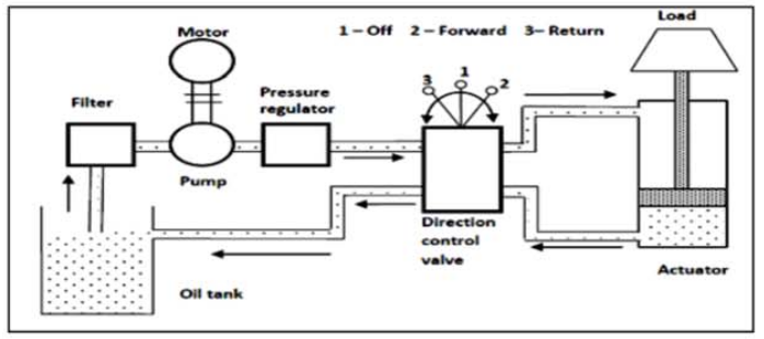
The main components and their functions in general layout hydraulic system
1.Oil tank : To act as reservoir for the working medium oil.The oil passes through various pipelines and after doing useful work in actuator; the oil returns back to oil tank. In the regions of low temperature, oil heaters are attached to oil tanks.
2. Filter : To prevent the foreign particles from entering into circuit.
3. Motor: To provide mechanical power to pump.
4.Pump : Hydraulic pump is heart of any hydraulic system. Its main function is to create the flow of oil under pressure through entire hydraulic system and hence to assist transfer of power and motion
5. Pressure regulator : To limit the pressure developed in the circuits to a limiting value. To drain oil to tank when pressure exceeds this limit.
6.Direction control valve; To change the direction of oil going to actuator.
7. Actuator ; To convert pressure energy of oil into mechanical work.
Q.2. Draw the general layout of Pneumatic system and its symbolic representation?
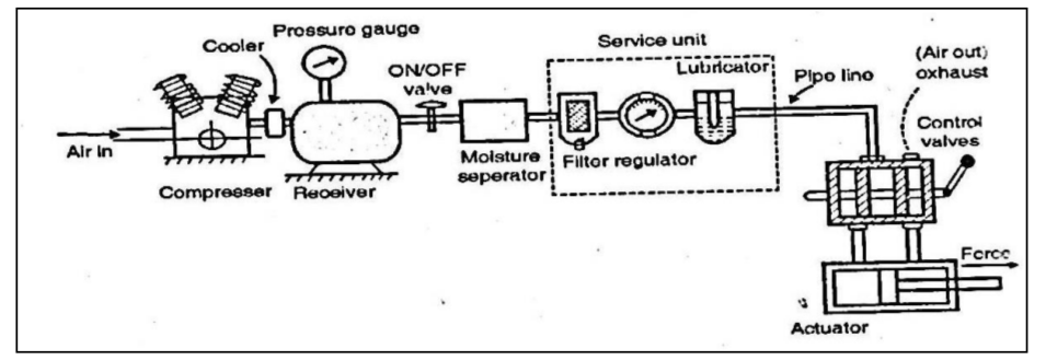
Ans : Pneumatic systems are the power transmitting assemblies employing pressurized air to transmit energy from an energy generating source to the application area. Pneumatic
system has air as the working medium (similar to electric current in electrical system, shafts gears and belts in mechanical system and air in a pneumatic system).
system has air as the working medium (similar to electric current in electrical system, shafts gears and belts in mechanical system and air in a pneumatic system).
The general structure of a pneumatic system is depicted in figure below.
Q.3. What is function of Oil reservoir,Pressure relief valve, Direction control valve and filters in Hydraulic system.
Ans :
(i) Oil Reservoir – To store the Hydraulic oil for the circuit
(ii) Pressure Relief Valve- To release the extra pressure whenever not required by system
(iii) Direction Control Valve- To give the direction to the actuator
(iv) Filters- To filter the foreign particle from the oil and to separates sub-micron level contamination
- Log in to post comments