You are here

4

A helical valve spring is to be designed for an operating load range of approximately 135 N. The deflection of the spring for the load range is 7.5 mm. Assume spring index of 10. Permissible shear stress for the material of the spring = 480 MPa and its mo

given load W= 135N Deflection ᵟ =7.5mm Spring index c=10 Permissible shear stress Ʈ=480 MPa Modulus of rigidity G =80 KN/mm2 Wahl’s factor K =4C-1/4C-4 +0.615/C=4X10-1/4X10-4 +0.615/10=1.14 (1)Mean dia. Of the spring coil (1 mark) Maximum shear stress, Ʈ = Kx 8WC/π d 2 480 = 1.14x 8x135x10/3.142xd2 d = 2.857mm from table we shall take a standard wire of size SWG 3 having diameters (d) =2.946mm mean dia. Of the spring coil D= CXd =10x2.946=29.46 mm outer dia.

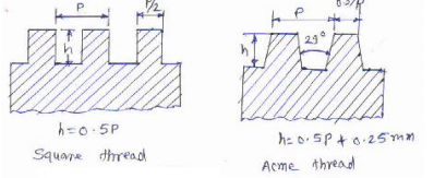
Define following terms w.r.t. bolts: 1) Major diameter 2) Minor diameter 3) Pitch 4) Lead

Definition w.r.t. bolts 1) Major dia.- dia. Of imaginary cylinder parallel with the crest of the thread ,it is the distance from crest to crest largest dia. of an external or internal thread 2) Minor dia.-dia. Of imaginary cylinder which just touches the roots of an external thread or smallest dia.of an external or internal screw thread 3) Pitch-distance from a point on one thread to the corresponding point on the next thread. 4) lead- distance between two corresponding points on the same helix

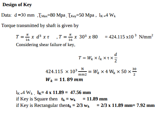
A shaft 30 mm. diameter is transmitting power.....................

Comparison of welded joints with screwed joint. 1) Welded Joint is rigid & permanent. Screwed joint is temporary. 2) Cost of welded assembly is lower than that of screwed joints. 3) Strength of welded structure is more than screwed joints. 4) For welding joints, highly skilled worker are required 5) Welded joints are tight & leak proof as compared to Screwed joints. 6) Welded joint is very difficult to inspect compared to other joints.


Compare welded joints with screwed joints. (Any six points)

Consideration in design of key: 1) Power to be transmitted. 2) Tightness of fit 3) Stability of connection 4) Cost 5) Crushing failure of key: 6) shearing failure of key 7) Material of key ,shaft should be same but key should be weaker than shaft .

Design a foot brake lever from the following data: Length of lever from C.G. of the spindle to the point of application of the load = 1 meter. Max. load on the foot plate = 800 N Overhang from the nearest bearing = 100 mm Permissible tensile and shear str

Methods of reducing stress concentration in cylindrical members with holes . Stress concentration can be reduced in cylindrical members with holes by providing additional holes in vicinity of holes as shown in fig. (ii). Fig (i) Showing cylindrical member with hole at center having stress line in disturb manner at vicinity of hole and component will fail at hole so for fig (i) ,stress concentration is more . fig. (ii) members shoulder having additional hole in vicinity of hole and therefore stress line maintain spacing between them so here stress concentration is less.

Pages

Subscribe to RSS - 4