You are here

6

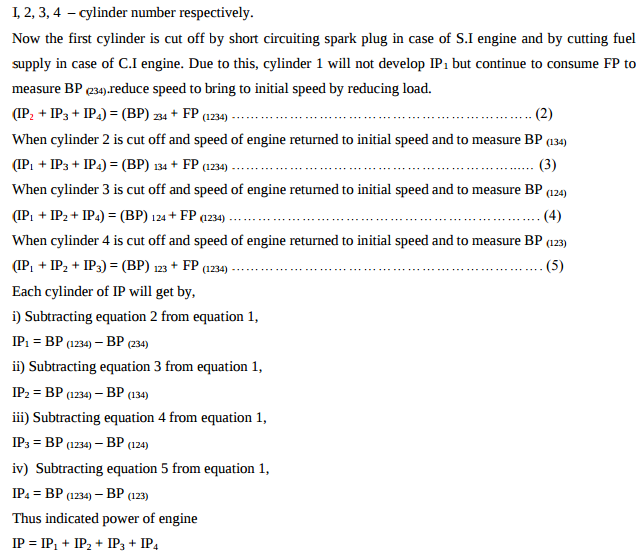
Explain in brief, how ‘Morse test’ is carried out ?

First engine is allowed to run at constant speed and brake power of engine is measured when all four cylinder working. (IP1 + IP2 + IP3 + IP4) = (BP) 1234 + (FP) 1234  Where, IP- indicated power. BP – brake power develop. FP – frictional power.

What is the meaning of unidirectional air motor and bi directional air motor.........

Operating or moving or allowing movement in one direction only. It runs in one direction only. It does not run in the other direction. Unidirectional motor can be operated by using 3/2 DC valve as shown in fig. Bidirectional air motor: Functioning or allowing movement in two usually opposite directions. It can runs in both direction. Bi-directional motor can be operated by using 4/3 DC valve as shown in fig

Explain with neat sketch the working of rotary spool type DC valve.

A rotary spool valve consists of a rotating spool which aligns with ports in stationary valve casing, so that fluid is directed to required port. A/B/P/R are the ports in casing. The port ‘P’ is a pressure port though which pressurized oil is coming in the valve. ‘R’ port is the port through which used oil is returning to oil tank. From fig port p is connected to port B and port A is connected to port R


Draw actual hydraulic system and explain its working.

Draw actual hydraulic system and explain its working. Oil hydraulics system uses pressurized oil which is circulated through various components of the hydraulic system to perform the given task. The various components of hydraulic system have to perform its intended function and they are arranged to form a layout of the system as per sequence of operation of hydraulic system. This arrangement of various hydraulic system components as per the nature of equipment/machine is known as actual layout of the system.

Explain with neat sketch the working of variable displacement vane pump.

) Explain with neat sketch working of variable displacement vane pump. In a hydraulic system the flow rate of the pump needs to be variable this can be easily achieved by varying the rpm of the electric motor. Other method is displacement of a vane inside the pump and therefore its delivery is proportional to the eccentricity between the rotor axis and cam ring. Changing the geometric position of the ring relative to the rotor center will change the delivery volume as per system need. Main components of the vane pumps are: 1. Hardened cam ring 2. Rotor 3. Vanes 4.

What is pressure compensated flow control valve ? Explain with sketch............

In any hydraulic circuit there are slight variations in presence of oil. When pressure changes the rate of flow changes but many circuits requires constant flow regardless of input or output pressure variations in the circuit then the pressure compensated FCV is used. It consists of hollow cylinder shaped poppet at the bottom of which there is a fixed orifice. There is a spring inside a poppet as shown in fig.

Explain working of counterbalance hydraulic circuit with neat diagram........

Counterbalance valves are commonly used to counterbalance a weight or external force or counteract a weight such as a platen or a press and keep it from freefalling.Figure1.16 illustrates  the use of a counterbalance or back-pressure valve to keep a vertically mounted cylinder in the upward position while the pump idles, that is, when the DCV is in its center position. During the downward movement of the cylinder, the counterbalance valve is set to open at slightly above the pressure required to hold the piston up (a check valve does not permit flow in this direction).

Pages

Subscribe to RSS - 6