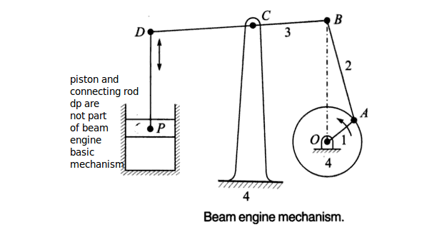
links -
Link 4 OC (frame)
Link 1 OA (Crank)
Link 2 AB (connecting Rod)
Link 3 BCD (lever)
Pairs -
Turning Pair = Frame OC & Crank OA
Turning Pair = Crank OA & Connecting Rod AB
Turning Pair = Connecting Rod AB & lever BCD
Turning Pair = Frame OC & lever BCD
Construction –
This mechanism is an inversion of four bar chain . It has four turning pair. It consists of frame OC which is fixed and on which all other elements are fitted. The Crank is fixed at pt. 'O' at frame. The crank is free rotates about pt.'O' . Other end of crank is connected to connectin rod AB. Other end of connecting rod AB is linked to one end of lever. The lever is pivoted at pt 'C' other end of lever 'D' is attached to piston -cylinder mechanism as shown.
Working –
As the crank starts rotating this motion is transmitted to lever by connection rod. As crank continues to rotate the lever starts to oscillate about pt. 'C', this oscillatory motion is transmitted to piston & cylinder.
Application – The mechanism converts rotary motion to reciprocating motion. This is used in machine tools & pumps. It is used for extracting oil from oil wells, the equipment is called Pump-jack.