Links -
1.Slider
2. Crank
3.Frame
4.Slotted Lever
Pairs-
Frame & Slotted lever – turning
Frame & Crank – turning
Crank & Slider – turning
Slider & Slotted lever - Sliding
Construction –
This mechanism is inversion of Single slider crank chain, which is obtained by fixing connecting rod of basic chain.It has three turning pair & one Sliding pair.
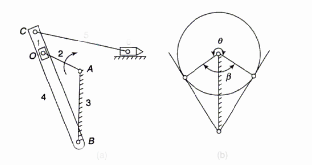
Crank is fitted to frame at pt.'A' & slotted lever is fitted to frame at pt.'B'. The crank & slotted lever are connected to each other through slider. The slider is free to slide in side slotted lever. The upper end of slotted lever is attached to the ram of shaping machine through a linkage {The ram and lever connecting to ram are not part of the basic inversion}
Working –
As the crank starts rotating about pt.'A', it also transmits motion to slider. As the slider is fitted inside the slotted lever, the slotted lever starts oscillating about pt.'B'.
As shown in second fig. The forward stroke is making an angle of ![]() Whereas the return stroke covers and angle of
Whereas the return stroke covers and angle of ![]() From the figure it is clear that angle
From the figure it is clear that angle ![]() hence forward stroke is takes more time than return stroke . Hence this mechanism is called as quick Return mechanism.
hence forward stroke is takes more time than return stroke . Hence this mechanism is called as quick Return mechanism.
Application –
The mechanism is used in shaping machine.