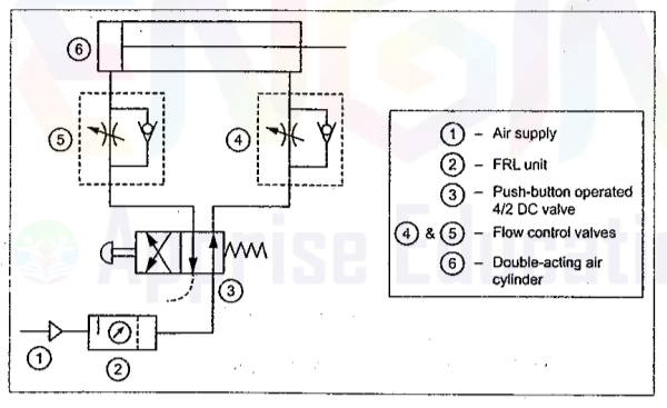
The above circuit uses a 4/2 manually operated dc valve to operate a double acting cylinder. Here two sets of metering valves with check valve are used which control the flow of air going to the cylinder. The speed control is achieved by controlling the air coming out from the cylinder. In the diagram shown during the return stroke the air will pass through the check valve of the valve set 4 but air coming out from the piston head side passes through the metering valve and thus the speed control is achieved. The above circuit is meter out type.
Q.2.Draw Pneumatic circuit for speed control of Bi-directional motor.
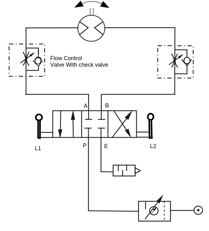
i-directional air motor rotates in clockwise as well as anti-clockwise direction. The speed of bidirectional motor is controlled as shown in fig. The speed control
of motor by using variable two flow control valves having built-in check valve and 4x3 DC valve having zero position or central hold position with lever L1 and L2. When lever L1 is operated, port P will be connected to port A of air motor and motor will start rotating in clockwise direction. Its speed can be controlled by using variable flow control valve F1. Port B of motor will be connected to exhaust E and air in motor will be exhausted through port R via DC valve. When
lever L2 is operated, pressure port P will be connected to port B of motor and naturally motor will start rotating in anticlockwise direction. Port A will be connected to port E and air in the motor will be exhausted through port E via DC valve.
Q.3.Explain with sketch Pneumatic sequencing circuit.
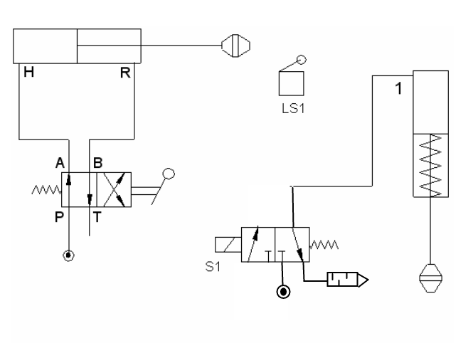
The above circuit shows the position based sequencing of two DA cylinders with use of 2/2 dc valves for pilot operating 4/2 valves. operated switch, which is triggered by a limit switch LS1. When the first cylinder reaches the limit it pushes the limit switch down thus providing current to solenoid switch S1, and there by shifting the dc valve. Due to shifting of dc valve the cylinder 2 starts moving down.
Q.4.Explain with sketch Pneumatic logic circuit “OR”
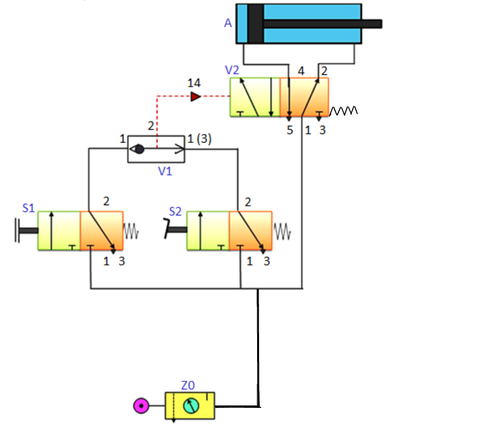
The above circuit represents the Pneumatic logic circuit 'OR', There are two 3/2 valves one is push button and another is pedal operated, the cylinder will be operated by pressing any one of them. That's why it is called OR circuit, means the DA cylinder will be actuated either by pressing pedal or push button. It uses a Shuttle valve which shifts depending upon the supply from either side. This provides pulse for the 5/2 pilot operated valve, which supplies air to the main cylinder
Q.5.Explain with sketch Pneumatic logic circuit “AND”

The above circuit represents the Pneumatic logic circuit 'AND', There are two 3/2 valves , the cylinder will be operated only when both the valves are pressed. That's why it is called AND circuit, means the DA cylinder will be actuated only when both the push buttons are pressed. It uses a Twin Pressure valve which provides supply to main valve when there is air supply from both valves . This provides pulse for the 5/2 pilot operated valve, which supplies air to the main cylinder.
Q.6.Explain with sketch Pneumatic 'TIME DELAY' circuit.
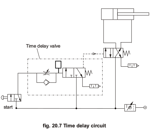
Time delay circuit as the name suggest is used to delay the effect of pushing button to some extent. In certain engineering applications, the impulse to the main valve is to be intendedly delayed by a pre-determined time for some operational or technical reasons. In such situations this valve is very useful.
As shown in circuit diagram it uses time delay valve which basically uses a metering valve and an accumulator which does not provide the impulse until the pressure is build up completely. Thus delaying the next operation after first button is pressed.
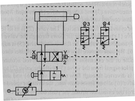
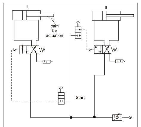
The figure shows a pilot-controlled automatic reciprocation circuit. When the tow way valve (1) is actuated, the cylinder will start reciprocating. Automatic cycling is achieved y using pilot air, directed alternatively through pilot air, directed alternatively through roller actuated three way valves (3 and 4) to shift the main control valve(2).
The main control valve(2) is in its left mode initially, by mechanically pressing the roller of valve 3, now the air enters the blank end of the cylinder and cylinder extends. At the end of extension, the pilot control valve (4) is tripped and air flows to the pilot chamber (Y) of the main control valve (2) . The valve (2) shifts to its right mode. Now cylinder starts retracting. At the end of retracting, the pilot valve(3) is tripped, causes the supply of air to X side of dc valve (2), shifting it to the left mode and cylinder starts extending.
- Log in to post comments