Question and answers
| Que.No | Marks | |
|---|---|---|
| Q 3 c ) |
4 |
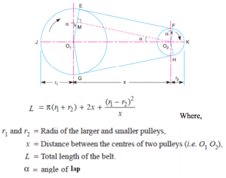
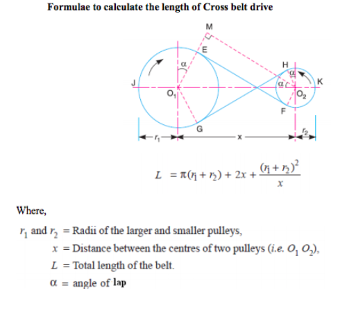
Question:State the formulae to calculate the length of open belt drive and cross belt drive. State the meaning of each term by drawing suitable diagrams in both cases.Answer: Formulae to calculate the length of open belt drive :
|
| Q 3 c ) |
4 |
Question:Prove that for square key equally strong in shear and crushing, the permissible crushing stress is twice the permissible shear stressAnswer:
|
| Q 3 d ) |
4 |
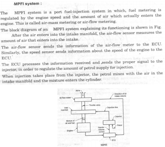
Question:Name the different sensors used in ECU of modern automobile with their application. (minimum 4Answer: Crank angle sensor: A permanent magnet inductive signal generator is mounted in close proximity to the flywheel, where it radiates a magnetic field. As the flywheel spins and the pins are rotated in the magnetic field, an alternating (AC) waveform is delivered to the ECM to indicate speed of rotation. Air Flow Sensor (AFS): The AFS is normally located between the air filter and the throttle body. As air flows through the sensor, it deflects a vane (flap) which wipes a potentiometer resistance track and so varies the resistance of the track and generates a variable voltage signal. Manifold absolute pressure (MAP) sensor: The MAP sensor measures the manifold vacuum or pressure, and uses a transducer to convert the signal to an electrical signal which is returned to the ECM. The unit may be designed as an independent sensor that is located in the engine compartment or integral with the ECM. Coolant temperature sensor (CTS): The CTS is a two-wire thermistor that measures the coolant temperature. The CTS is immersed in the engine coolant, and contains a variable resistor that usually operates on the NTC principle. Throttle Position Sensor (TPS): TPS is provided to inform the ECM of idle position, deceleration, rate of acceleration and wide-open throttle (WOT) conditions. The TPS is a potentiometer which varies the resistance and voltage of the signal returned to the ECM. Oxygen sensor (OS): An oxygen sensor is a ceramic device 'placed in the exhaust manifold on the engine side of the catalytic converter. The oxygen sensor returns a signal to the ECM, which can almost instantaneously (within 50 ms) adjust the injection duration. ----------------------------------------------------------------------------------------------------- |
| Q 3 d ) |
4 |
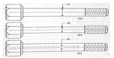
Question:Explain with neat sketch the bolts of uniform strength.Answer:
In an ordinary bolt shown in Fig. (a), the effect of the impulsive loads applied axially is concentrated on the weakest part of the bolt i.e. the cross-sectional area at the root of the threads. In other words, the stress in the threaded part of the bolt will be higher than that in the shank. Hence a great portion of the energy will be absorbed at the region of the threaded part which may fracture the threaded portion because of its small length. If the shank of the bolt is turned down to a diameter equal or even slightly less than the core diameter of the thread (d) as shown in Fig. (b), then shank of the bolt will undergo a higher stress. This means that a shank will absorb a large portion of the energy, thus relieving the material at the sections near the thread. The bolt, in this way, becomes stronger and lighter and it increases the shock absorbing capacity of the bolt because of an increased modulus of resilience. This gives us bolts of uniform strength. The resilience of a bolt may also be increased by increasing its length. A second alternative method of obtaining the bolts of uniform strength is shown in Fig. (c). An axial hole is drilled through the head as far as the thread portion such that the area of the shank becomes equal to the root area of the thread ----------------------------------------------------------------------------------------------------- |
| Q 3 d ) |
4 |
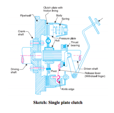
Question:Draw the neat sketch of single plate clutch and explain its working.Answer:
|
| Q 3 e ) |
4 |
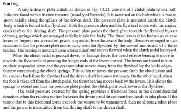
Question:Explain different stages of combustion in C.I. engine with sketch.Answer: 1) Ignition delay period : During this fuel has already admitted but has not yer ignited. This is counted from start of injection to the point where P-O curve separates from pure air compression curve. 2) Rapid or uncontrolled combustion : In this stage pressure rise because of during the delay period the fuel droplet have time to spread over a wide area and fresh air around them. 3) Controlled combustion : The temperature and pressure rise in the second state is quite high, hence droplet of fuel injected in stage burn faster with reduced ignition delay as soon as they find necessary oxygen and further pressure rise is controlled by injection rate. 4) After burning : This sage may not be present in all cases. Because of poor distribution of fuel particles, combustion continues during part of the remainder of the expansion stroke.
|
| Q 3 e ) |
4 |
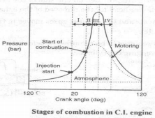
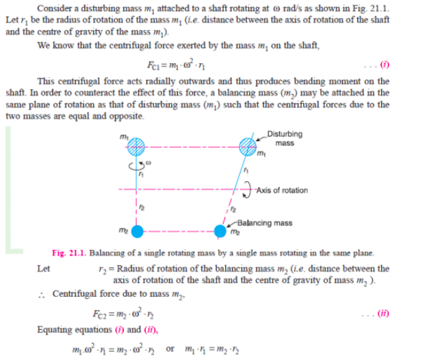
Question:State the procedure of balancing single rotating mass when its balancing mass is rotating in the same plane as that of disturbing mass.Answer:
|
| Q 3 e ) |
4 |
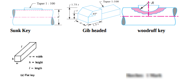
Question:How keys are classified? Give detailed classification of keys with neat sketches; also state their applications.Answer: Keys are classified on the basis of shape and application of keys.………………are 1) Sunk Key : a) Rectangular sunk key b) square sunk key c) Gib head key d) feather key e) Woodruff key 2) Saddle key a) Flat saddle key b) hollow saddle key 3) Round key 4) Splines …………………: 1) Sunk Key : used for heavy duty application a) Rectangular sunk key : for preventing rotation of gears and pulleys on shaft b) Gib headed key: used where key to be removed frequently. c) feather key: Machine tool 2) Saddle key: for light duty or low power transmission 3) Round key : Used for low Power drive 4) Splines: Where providing axial movement between shaft and mounted member
----------------------------------------------------------------------------------------------------- |
| Q 3 f ) |
4 |
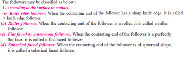
Question:Give detailed classification of followers.Answer:
|
| Q 4 a ) |
4 |
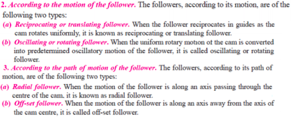
Question:What is centrifugal tension ? State its formula. Explain its effect on power transmitted by a belt drive.Answer:
|
| Q 4a)(a) |
4 |
Question:Explain MPFI system with sketchAnswer:
|
| Q 4a)(b) |
4 |
Question:Define the following related I.C. engine. i) Indicated power ii) Brake power iii) Brake specific fuel consumption iv) Relative efficiency.Answer: i) Indicated Power (ip) is defined as the power developed by combustion of fuel in the cylinder of engine. It is always more than brake power. ii Brake Power:- The useful power which is available at the crank shaft is called as brake power. It is denoted by “B.P.” It has unit kW iii) B.S.F.C: It is the weight of fuel required to develop 1KW of the brake power for period of 1 hour. Unit of B.S.F.C is Kg/KWh. It is defined as the amount of fuel consumed per unit of break power developed per hour.
iv) Relative efficiency is defined as the ratio of indicated / brake thermal efficiency to the air standard efficiency. ----------------------------------------------------------------------------------------------------- |
| Q 4a)(c) |
4 |
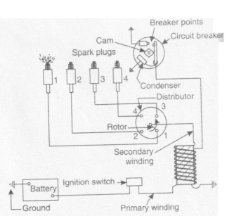
Question:Draw and explain Battery ignition system.Answer: Battery Ignition system : I t consists of six or twelve volt battery, ignition switch,induction coil, circuit breaker condenser and distributor. All the circuit parts are shown in figure. One terminal of battery is ground to engine frame and other is connected through the ignition switch to one primary terminal of induction coil. The other primary connection is connected to one end of contact point of circuit breaker and through closed points to ground. The ignition switchis made on and engine is crancked. When the contacts touch, the current flows the battery to the switch. Due to this primary winding of induction coil to circuit breaker points and circuit is completed. A condenser prevents sparking of this point. The rotating cam breaks open the contacts immediately and breaking of this primary circuit brings about change of magnetic field causing very high volt about 8000 to 12000 volts. Due to this high voltage the spark jumps across the gap in the spark plug and thereby it ignites mixture of air and fuel.
|
| Q 4a)(ii) |
4 |
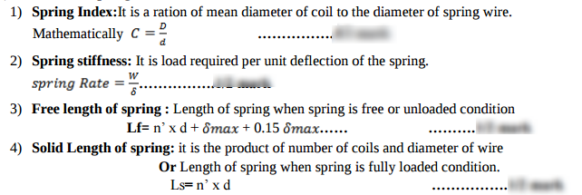
Question:: (1) Spring index (2) Spring stiffness (3) Free length of spring (4) Solid length of springAnswer:
|
| Q 4a)(iv) |
4 |
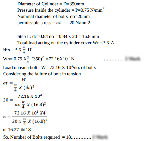
Question:A cylinder head of steam engine is held in position by M20 bolts. The effective diameter of cylinder is 350 mm and the steam pressure is 0.75 N/mm2. If the bolts are not initially stressed, find the number of bolts required. Take working stress for bolt material as 20 N/mm2.Answer:
|
| Q 4a)(l) |
4 |
Question:State the meaning of following colour codes in aesthetic consideration while designing the product: (1) Red (2) Orange (3) Green (4) BlueAnswer: 1) Red: Danger,Hot 2) Orange: Possible Orange 3) Green : Safe 4) Blue: Cold ----------------------------------------------------------------------------------------------------- |
| Q 4 b ) |
4 |
Question:State the meaning of sliding pair, turning pair, rolling pair and spherical pair with one example each.Answer:
|
| Q 4b)(a) |
6 |
Question:List the additives of Lubricant used in S.I. engine and state their advantages.Answer: Role of following lubricant additives (one mark each) 1. Zinc ditinophosphate: - Zinc ditinophosphate serves as an anti – oxidant and anticorrosive additive. 2. Fatty acids: - This type of additives prevents rusting of ferrous engine parts during and form acidic moisture accumulation during cold engine operation. 3. Organic Acids: - This type of additives improves the detergent action of lubricating oil. 4. Ester: - To lower the pour point of lubricating oil. 5. Silicon polymers: - This additive serves as Antifoam Agent. 6. Butylene polymers: - This type of additives added in lubricating oil to increase their viscosity index. 7. Zinc ditinophosphate: - Zinc ditinophosphate serves as an anti – oxidant and anticorrosive additive. 8. Fatty acids: - This type of additives prevents rusting of ferrous engine parts during and form acidic moisture accumulation during cold engine operation. 9. Organic Acids: - This type of additives improves the detergent action of lubricating oil. 10. Ester: - To lower the pour point of lubricating oil. 11. Silicon polymers: - This additive serves as Antifoam Agent. 12. Butylene polymers: - This type of additives added in lubricating oil to increase their viscosity index. ----------------------------------------------------------------------------------------------------- |
| Q 4b)(b) |
6 |
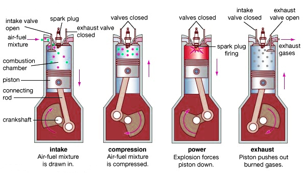
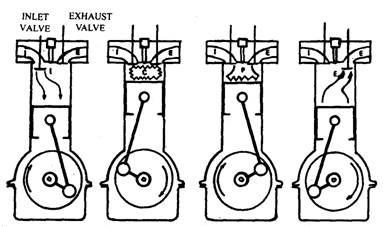
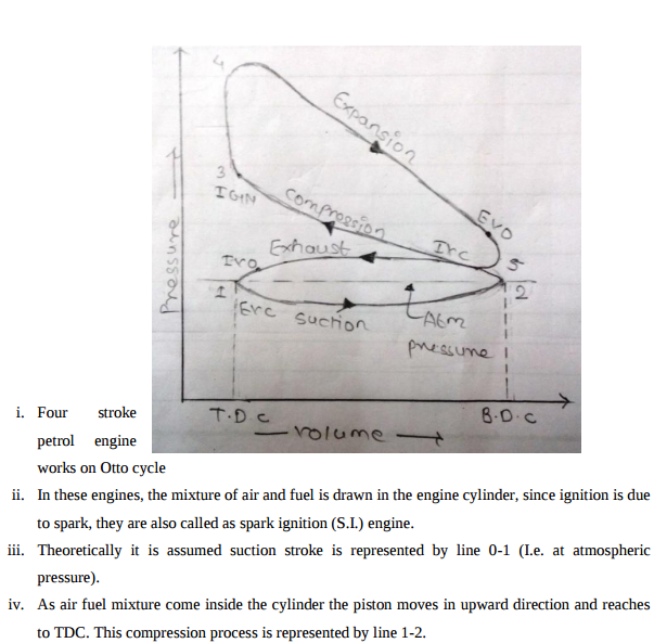
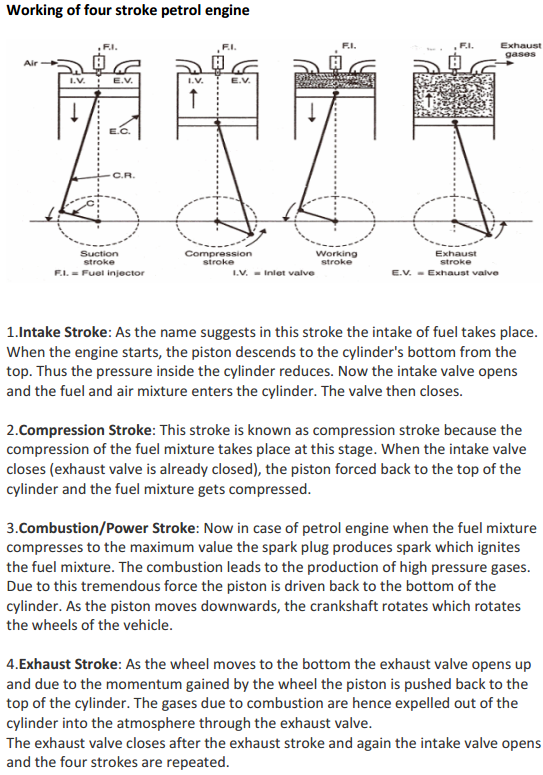
Question:Explain working of 4 stroke S.I. engine with neat sketch. or With neat sketches explain the working principle of four stroke spark ignition engine.Answer: Four stroke spark ignition engine working principle
Four stroke spark ignition engine working principle.Four stroke spark ignition engine is given below in 4 steps, 1. Suction stroke: Suction stroke starts when piston is at top dead center and about to move downwards. During suction stroke inlet valve is open and exhaust valve is closed. Due to low pressure created by the motion of the piston towards bottom dead center, the charge consisting of fresh air mixed with the fuel is drawn into cylinder. At the end of suction stroke the inlet valve closes. 2. Compression stroke: During compression stroke, the compression of charge takes place by return stroke of piston, i.e. when piston moves from BDC to TDC. During this stroke both, inlet and exhaust valve remain closed. Charge which is occupied by the whole cylinder volume is compressed up to the clearance volume. Just before completion of compression stroke, a spark is produced by the spark plug and fuel is ignited. Combustion takes place when the piston is almost at TDC. 3. Expansion or power stroke: Piston gets downward thrust by explosion of charge. Due to high pressure of burnt gases, piston moves downwards to the BDC. During expansion stroke both inlet and exhaust valves remains closed. Thus power is obtained by expansion of products of combustion. Therefore it is also called as ‘power stroke’. Both pressure as well as temperature decreases during expansion stroke. 4. Exhaust stroke: At the end of expansion stroke the exhaust valve opens, the inlet valve remains closed and the piston moves from BDC to TDC. During exhaust stroke the burnt gases inside the cylinder are expelled out. The exhaust valve closes at the end of the exhaust stroke but still some residual gases remains in cylinder. ======================Answer ends here================== Additional information about Four stroke spark ignition engine for better understanding
----------------------------------------------------------------------------------------------------- |
| Q 4b)(i) |
6 |
Question:State the different modes of failure of gear teeth and their possible remedies to avoid the failure.Answer: 1. Bending failure. 2. Pitting. 3. Scoring. 4. Abrasive wear. 5. Corrosive wear Remedies to avoid failure: 1. Bending failure. In order to avoid such failure, the module and face width of the gear is adjusted so that the beam strength is greater than the dynamic load. 2. Pitting. In order to avoid the pitting, the dynamic load between the gear tooth should be less than the wear strength of the gear tooth. 3. Scoring. This type of failure can be avoided by properly designing the parameters such as speed, pressure and proper flow of the lubricant, so that the temperature at the rubbing faces is within the permissible limits. 4. Abrasive wear. This type of failure can be avoided by providing filters for the lubricating oil or by using high viscosity lubricant oil which enables the formation of thicker oil film and hence permits easy passage of such particles without damaging the gear surface. 5. Corrosive wear.. In order to avoid this type of wear, proper anti-corrosive additives should be used. ----------------------------------------------------------------------------------------------------- |
| Q 4b)(ii) |
6 |
Question:Explain the following types of stresses: (1) Transverse shear stress (2) Compressive stress (3) Torsional shear stressAnswer: When a section is subjected to two equal and opposite forces acting tangentially across the section such that it tends to shear off across the section. The stress produces is called as transverse shear stress. …………………… From figure Mathematically transverse shear stress is represented as, τ = / Where, F = Tangential force applied A = Area of cross section = ( /4 ) 2 d = Diameter of rivet. ……………………ii )Compressive Stress: When a body is subjected to two equal & opposite axial pushes ,then the internal resistances set up in the material is called as compressive stress.……………………It is denoted by σc σc =P/A Where ,P: Axial compressive force ,A : Cross Sectional Area.…………… iii) Torsional stress: When a machine component is under the action of two equal and opposite couples i.e. twisting moment or torque, then component is said to be torsional and the stresses set up due to torsion are called as torsional shear stress. ……………………Consider a component of circular cross-section. ‘d’ in diameter, subjected to torque T, Torsional shear stress is given by, basic torsion equation /J = / =Gθ/L τ = . / J Where, r = distance of outer fibre from neutral axis = d/2 J = Polar moment of inertia of cross- section = ( /64)4…………………… ----------------------------------------------------------------------------------------------------- |
| Q 4 c ) |
4 |
Question:Draw turning moment diagram for single cylinder four stroke I.C. Engine. Label all parts.Answer: ----------------------------------------------------------------------------------------------------- |
| Q 4 d ) |
4 |
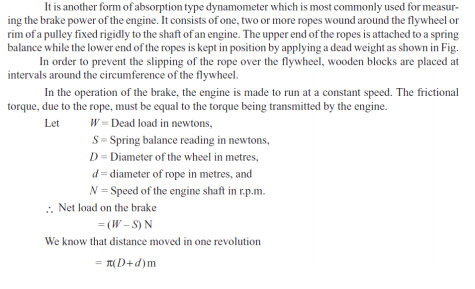
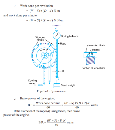
Question:Explain the working of rope brake dynamometer with neat sketch.Answer:
|
| Q 4 e ) |
4 |
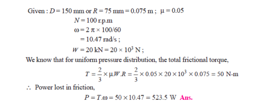
Question:A vertical shaft 150 mm in diameter and rotating at 100 rpm rests on a flat end footstep bearing. The shaft carries vertical load of 20 kN. Assuming uniform pressure distribution and coefficient of friction equal to 0.05, estimate power lost in frictionAnswer:
|
| Q 4 f ) |
4 |
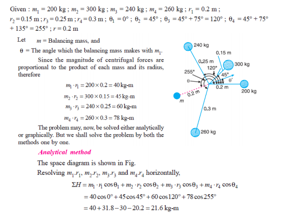
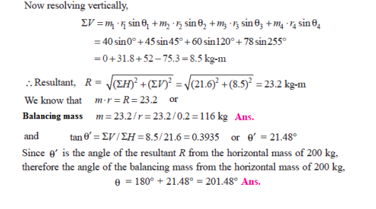
Question:Four masses m1, m2, m3 and m4 are 200 kg, 300 kg, 240 kg, and 260 kg respectively. The corresponding radii of rotation are 0.2 m, 0.15 m, 0.25 m and 0.3 m respectively and the angles between successive masses are 45°, 75° and 135°. Find the position and magnitude of balance mass required, if its radius of rotation is 0.2 m.Answer:
|
| Q 5 a ) |
4 |
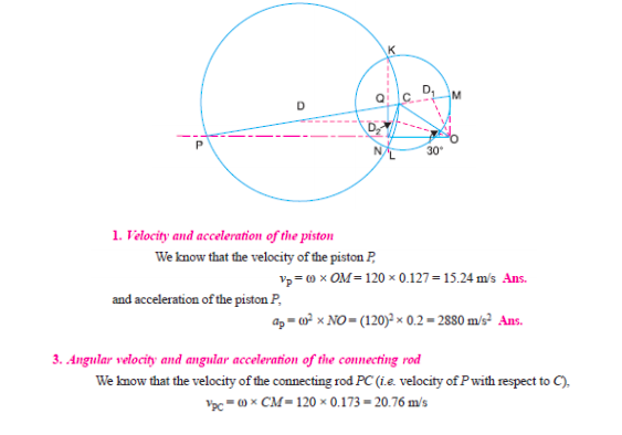
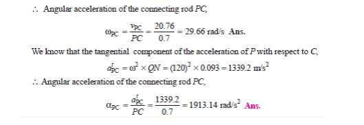
Question:The crank and connecting rod of a reciprocating engine are 200 mm and 700 mm respectively. The crank is rotating in clockwise direction at 120 rad/s. Draw Klein’s construction and find (i) Velocity and acceleration of the piston (ii) Angular velocity and angular acceleration of the connecting rod at the instant when the crank is at 30° to IDC (inner dead centre).Answer: Construction :
----------------------------------------------------------------------------------------------------- |
| Q 5 a ) |
8 |
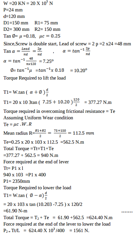
Question:A vertical double start square threaded screw of 120 mm mean diameter and 24 mm pitch supports a vertical load of 20 kN. The axial thrust in screw is taken by collar bearings of 300 mm outside and 150 mm inside diameter. Find the force required at the end of the lever which is 400 mm long in order to lift and lower the load. The coefficient of friction for screw and nut is 0.18 and for collar bearing it is 0.25.Answer:
|
| Q 5 a ) |
8 |
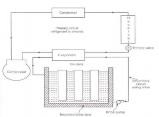
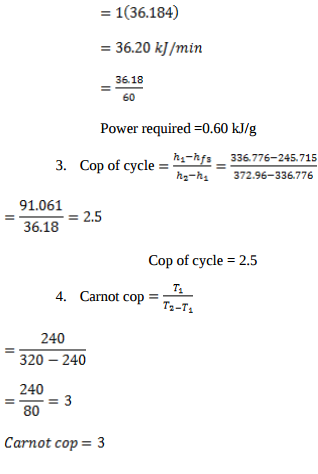
Question:Explain construction and working of ice plant with neat sketch.Answer: The main cycle used for ice plant is vapor compression cycle with ammonia as the refrigerant in primary circuit and brine solution in secondary circuit. Brine solution takes heat from water in secondary circuit and delivers the heat to ammonia in primary circuit. Thus, the indirect method of cooling is used in ice plant. In secondary circuit brine is cooled in evaporator and then it is circulated around the can which contains water. The heat is extracted from the water in the can and is given to the brine. The brine is contentiously circulated around the can with the help of brine pump till entire water in the can is converted into ice at -6 0 C. Ammonia vapor coming out of evaporator is compressed to high pressure and then these vapors are condensed in the condenser. High pressure liquid ammonia is collected in the receiver and it is passed through the expansion valve to reduce its pressure and temperature as per requirement. The throttle liquid ammonia at low temperature & low pressure enters in evaporator, which are the coils dipped in brine tank. The liquid ammonia absorbs heat from brine and gets converted into vapors, which are drawn by suction line of compressor.
|
| Q 5 b ) |
8 |
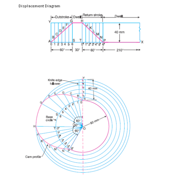
Question:A cam is to give the following motion to a knife edged follower : (i) Outstroke during 60° of cam rotation. (ii) Dwell for the next 30° of cam rotation. (iii) Return stroke during next 60° of cam rotation. iv) Dwell for the remaining 210° of cam rotation. The stroke of the follower is 40 mm and the minimum radius of the cam is 50 mm. The follower moves with uniform velocity during both the outstroke and return stroke. Draw the profile of the cam when the axis of the follower passes through the axis of the camshaft.Answer:
|
| Q 5 b ) |
8 |
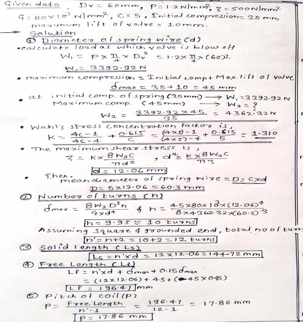
Question:A safety valve of 60 mm diameter is to blow off at a pressure of 1.2 N/mm2. It is held on its seat by a close coiled helical spring. The maximum lift of the valve is 10 mm. Design a suitable compression spring of spring index 5 with an initial compression of 35 mm. The shear stress for spring material is limited to 500 MPa. Take G = 80 kN/mm2.Answer:
|
| Q 5 b ) |
8 |
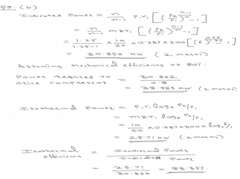
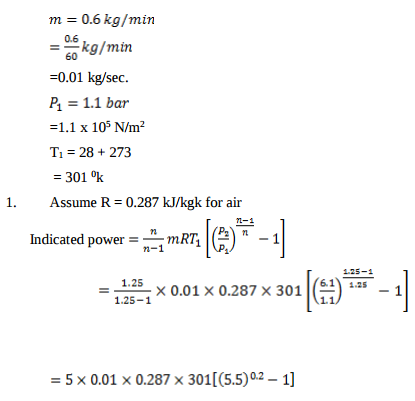
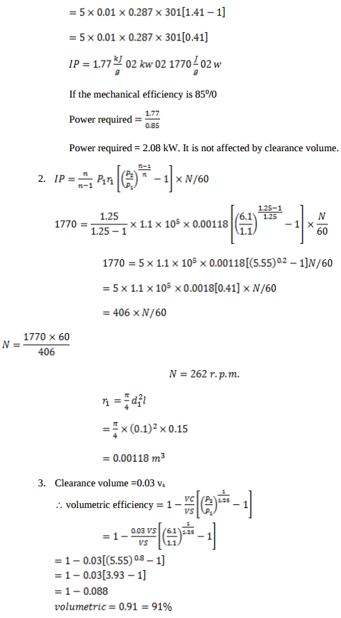
Question:A pneumatic rock drill requires 10 kg/min of air at 6 bar pressure. Find the power required to drive the single acting single stage reciprocating compressor receiving air at 1 bar and 27°C. Assume mechanical efficiency as 80% and value of index, n as 1.25. Take Cp = 1.005 kJ/kgk and Cv = 0.718 kJ/kgk for air. Also estimate isothermal efficiency of compression.Answer:
|
| Q 5 c ) |
8 |
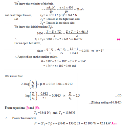
Question:Two parallel shafts whose centre line are 4.8 m apart, are connected by open belt drive. The diameter of larger pulley is 1.5 m and that of smaller pulley 1 m. The initial tension in the belt when stationary is 3 kN. The mass of the belt is 1.5 kg/m length. The coefficient of friction between the belt and pulley is 0.3 Taking centrifugal tension into account, calculate the power transmitted when the smaller pulley rotates at 400 rpm.Answer:
|
| Q 5 c ) |
4 |
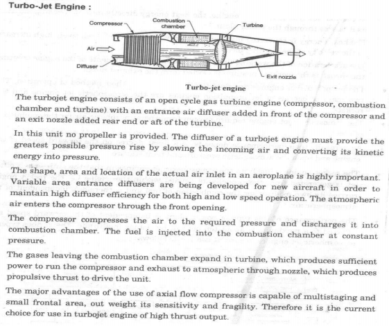
Question:Explain construction and working of turbojet with neat labelled sketchAnswer:
|
| Q 5c)(ii) |
8 |
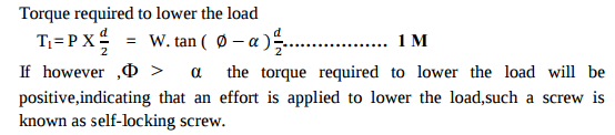
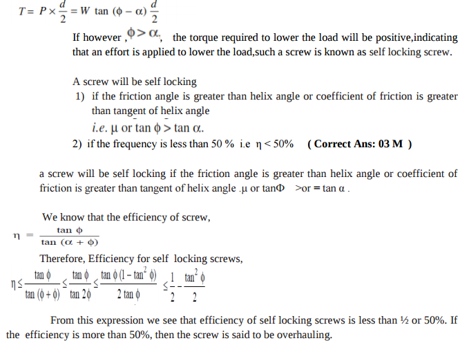
Question:Explain the terms self locking and overhauling of screw.Answer:
|
| Q 5c)(l) |
6 |
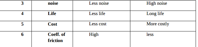
Question:Differentiate between sliding contact and rolling contact bearings. (any four points of difference)Answer:
|
| Q 6 a ) |
4 |
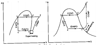
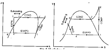
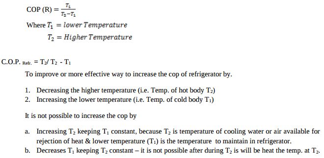
Question:Represent subcooling and superheating on P-h and T-S diagram in refrigeration also give its effect on C.O.P. of refrigeration.Answer: Superheating
Due to superheating suction temperature of compressor increases , increasing compressor power but it also increases the refrigerating effect therefore COP of system remains more or less constant. The superheating is not done to increase the refrigerating effect or COP but it is done to increase the life of compressor.
The process of cooling refrigerant below condensing temperature for a given pressure is known as sub-cooling. Due to sub-cooling the refrigerating effect increases or for same refrigerating effect the circulation rate refrigerant decreases and therefore COP of system increases. Thus sub-cooling is desirable & is done to increase refrigerating effect & COP of system. ----------------------------------------------------------------------------------------------------- |
| Q 6a)(i) |
4 |
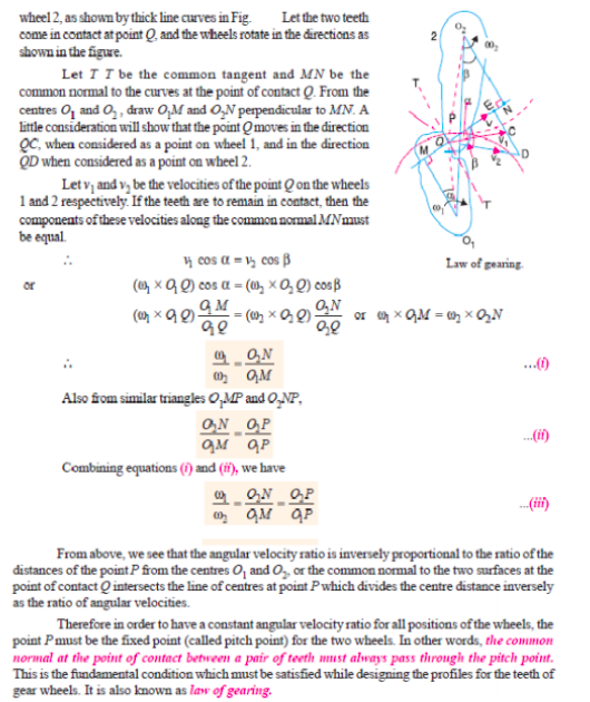
Question:State and explain law of gearing with the help of suitable sketch.Answer:
|
| Q 6a)(ii) |
4 |
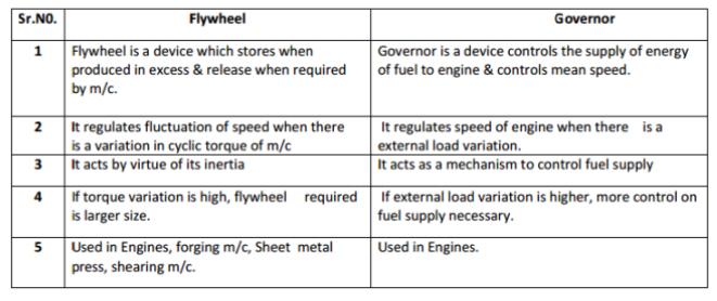
Question:Compare flywheel and governor.Answer:
|
| Q 6 b ) |
8 |
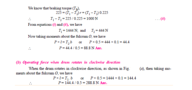
Question:In a simple band brake, the band acts on the 3/4th of circumference of a drum of 450 mm diameter which is keyed to the shaft. The band brake provides a braking torque of 225 N.m. One end of the band is attached to a fulcrum pin of the lever and the other end to a pin 100 mm from the fulcrum. It the operating force is applied at 500 mm from the fulcrum and the coefficient of friction is 0.25, find the operating force when the drum rotates in the (i) anticlockwise direction and ii) clockwise directionAnswer:
|
| Q 6 b ) |
8 |
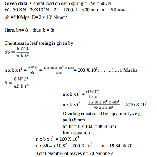
Question:A semi-elliptical carriage spring of 1200 mm length withstands a load of 60 kN with maximum deflection of 90 mm. Assume breadth to thickness ratio as 8. Design the spring if bending stress of spring material is 540 MPa and E = 2 × 10⁵ N/mm2.Answer:
|
| Q 6 b ) |
4 |
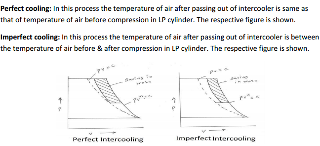
Question:Define perfect and imperfect inter-cooling in air compressor and show it by graph alsoAnswer:
|
| Q 6 c ) |
8 |
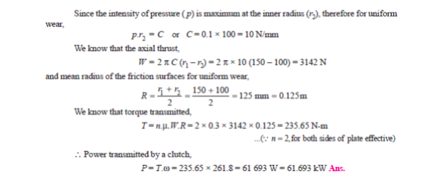
Question:A single plate clutch with both sides effective has outer and inner diameters 300 mm and 200 mm respectively. The maximum intensity of pressure at any point in the contact surface is not to exceed 0.1 N/mm2. If the coefficient of friction is 0.3, determine the power transmitted by a clutch at a speed of 2500 rpm. Assume uniform condition.Answer: Single Plate Clutch:
|
| Q 6 c ) |
8 |
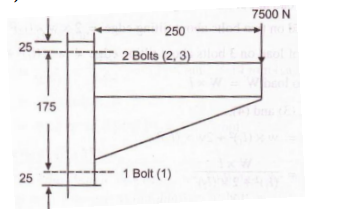
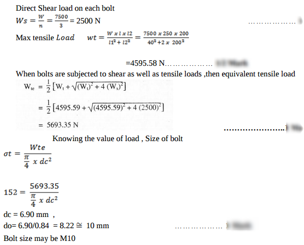
Question:A wall bracket is fixed to the wall by means of three bolts, one bolt at a distance of 25 mm from the lower edge and remaining two bolts at a distance of 175 mm from the lower bolts. It supports a load of 7.5 kN at a distance of 250 mm from the wall. The bolts are made from plain carbon steel 45C8 with tensile yield strength of 380 N/mm2. If factor of safety is 2.5, estimate the size of the bolts. Sketch the arrangementAnswer:
|
| Q 6 c ) |
4 |
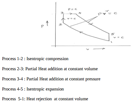
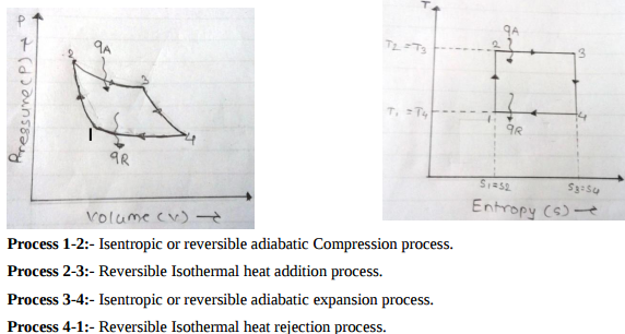
Question:Draw P-V and T-S diagram for dual cycle. Name the processes involved in it.Answer:
|
| Q 6 d ) |
8 |
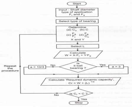
Question:Explain the selection procedure of bearings from manufacturer’s catalogue.Answer: 1) Calculate radial and axial forces and determine dia. of shaft. 2) Select proper type of bearing. 3) Start with extra light series for given diagram go by trial of error method. 4) Find value of basic static capacity (co) of selected bearing from catalogue. 5) Calculate ratios Fa/VFr and Fa/Co. 6) Calculate values of radial and thrust factors.(X & Y) from catalogue. 7) For given application find value of load factor Ka from catalogue. 8) Calculate equivalent dynamic load using relation. Pe = (XVFr + YFA) Ka. 9) Decide expected life of bearing considering application. Express life in million revolutions L10. 10) Calculate required basic dynamic capacity for bearing by relation. 11) Check whether selected bearing has req. dynamic capacity, IF it not select the bearing of next series and repeat procedure from step-4.
|
| Q 6 d ) |
4 |
Question:Give classification of air conditioning system.Answer: Air conditioning systems are classified as 1) Classification as to major function- i) Comfort air-conditioning - air conditioning in hotels, homes, offices etc. ii) Commercial air-conditioning- air conditioning for malls, super market etc ii) Industrial air-conditioning – air conditioning for processing, laboratories etc 2) Classification as to season of the yeari) Summer air-conditioning - These system control all the four atmospheric conditions for summer comfort. ii) Winter air-conditioning – This system is designed for comfort in winter. iii) Year round air-conditioning – These system consists of heating and cooling equipments with automatic control to produce comfortable condition throughout the year 3) Classification as to Equipment Arrangementi) Unitary system ii) Central system ----------------------------------------------------------------------------------------------------- |
| Q 6 e ) |
4 |
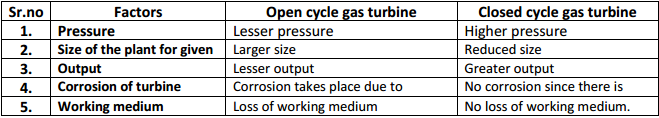
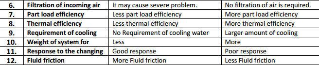
Question:Compare, closed cycle and open cycle gas turbine (any four point)Answer:
|
| Q 6 e ) |
8 |
Question:State the applications of following bearings with suitable reasons: (i) Deep grove ball bearing (ii) Taper roller bearing (iii) Thrust coller bearing (iv) Needle roller bearingAnswer: i) Deep Groove Ball bearing : Application: Electric Motor Reason: Capacity to take heavily axial load with high rotational speed ii) Taper roller bearing : Application: axle housing of automobile Reason: ability to take high radial load as well as thrust load iii) Thrust collar bearing: Application: Clutch of automobile Reason: ability to combine radial & axial load with min. speed iv) Needle roller bearing: Application: Differential of automobile Reason: takes less radial space. it has high radial load carrying capacity. ----------------------------------------------------------------------------------------------------- |
| Q 6 f ) |
4 |
Question:State the different methods used to improve thermal efficiency of gas turbine. Explain any one in brief.Answer: Methods to improve thermal efficiency of gas turbine 1) Regeneration – This is done by preheating the compressed air before entering to the combustion chamber with the turbine exhaust in a heat exchanger, thus saving fuel consumption.
|


| Que.No | Marks | |
|---|---|---|
| Q 1a)(i) |
4 |
Question:Why does the Carnot heat engine not exist in practice? Give any four pointsAnswer: Carnot heat engine is an ideal heat engine and is not possible in practice due to following reasons. i) Alternate adiabatic and isothermal process is not possible. ii) Heat addition and heat rejection at constant temperature is not possible. iii) All processes are reversible which is not possible in practice ----------------------------------------------------------------------------------------------------- |
| Q 1a)(ii) |
4 |
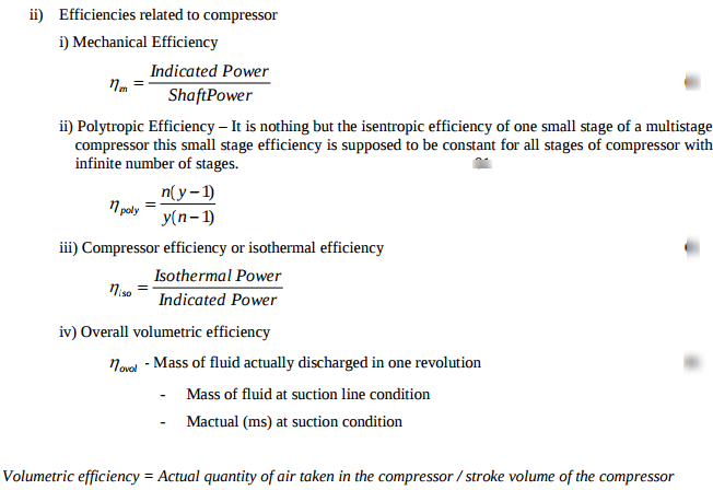
Question:Define following efficiencies related to compressors: 1) mechanical efficiency 2) polytropic efficiency 3) compressor efficiency 4) overall volumetric efficiencyAnswer:
|
| Q 1a)(iii) |
4 |
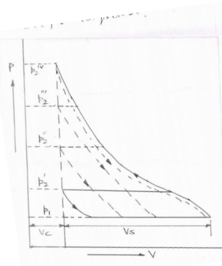
Question:Show the effect of increase of compression ratio in a single stage reciprocating compresor on PV diagram and give its physical significance.Answer: Effect of Compression ratio in a single stage reciprocating compressor on PV diagram
Physical Significance:- If compression in increased (usually it varies from 5 to 8) the final temperature increases and volumetric efficiency decreases flow and it compression ratio increases beyond usual value, compression ratio P2/P1 becomes zero as it can be observed from the figure. Increment in compression ratio will increase leakage past the piston and will need robust cylinder. If will also affect the operation of delivery valve and if will reduce lubricating properties of oil. It may increase the risk of ignition in piping and receiver. ----------------------------------------------------------------------------------------------------- |
| Q 1a)(iv) |
4 |
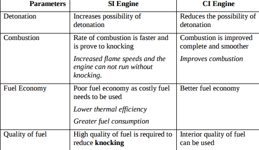
Question:Compare the effect of supercharging on S.I. engine and C.I. engine with respect to following parameters: 1) detonation 2) combustion 3) fuel economy 4) quality of fuel.Answer: Effect of Supercharging on SI and CI engine
|
| Q 1b)(i) |
6 |
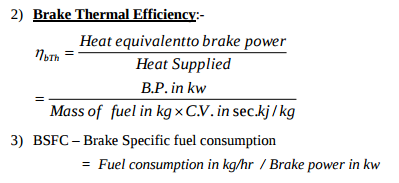
Question:What do you mean by: 1) frictional power 2) brake thermal efficiency 3) BSFC, w.r.to I.C. engineAnswer: 1) Friction Power:- The difference between indicated power and brake power. It is the power lost in friction FP =IP -BP
|
| Q 1b)(ii) |
6 |
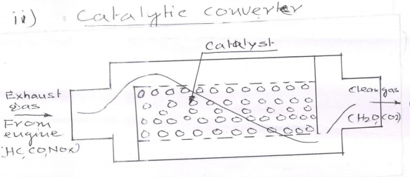
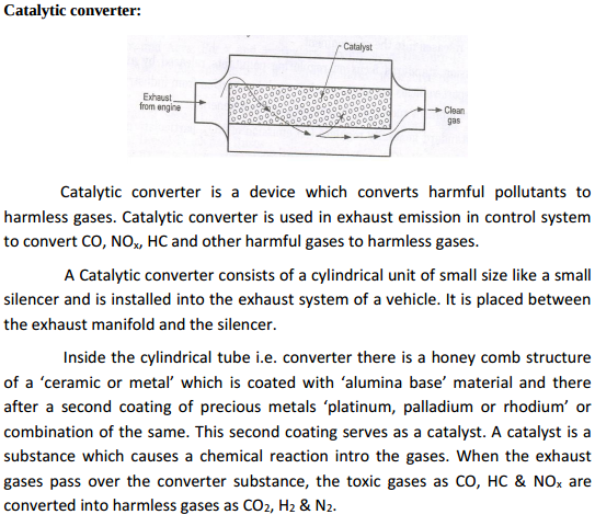
Question:Explain with neat sketch any one catalytic converterAnswer:
Fig. shows construction of simple catalytic converter exhaust fan as it enters the converter all three pollutions namely HC CO and NOX oxidizes and reduce is to the component which are acceptable to the environment, This occurs due to chemical reaction and at 600 to 7000 c temperature. ----------------------------------------------------------------------------------------------------- |
| Q 2a)(i) |
8 |
Question:The criterion of the thermodynamic efficiency of a reciprocating compressor is isothermal compression while for rotory compressor it is isentropic compression. Discuss the reason for this.Answer: The compression process in reciprocating compressor may approach to low speed of compression and cylinder cooling. Therefore isothermal efficiency is used in reciprocating compressor. But in rotary compressor there is high friction and eddies formation due to high velocity air through the compressor. This causes heating of air during compression process. Therefore temperature of air leaving the impeller is higher than the isentropic compression. The compressor may be as high as 1.7 (n>t). Therefore isentropic efficiency is used in rotary compressor. ----------------------------------------------------------------------------------------------------- |
| Q 2a)(ii) |
8 |
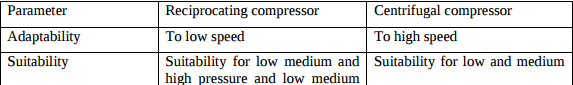
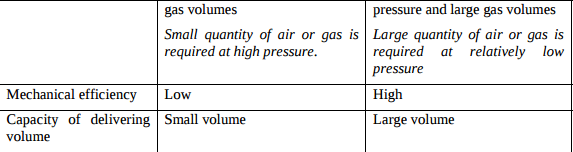
Question:Compare reciprocating compressors and centrifugal compressors on the basis of the following parameters: 1) adaptability 2) suitability 3) mechanical efficiency 4) capacity of delivering volume.Answer:
|
| Q 2b)(i) |
8 |
Question:Define: 1) DPT 2) WBT 3) DBT 4) moist air.Answer: DPT – Dew point temperature tDP - It is the temperature at which air water vapour mixture starts to condense. 01 D.P.T. of mixture is defined as the temperature at which water vapours starts to condense. WBT - Wet bulb temperature - tWB 01 - It is the temperature recorded by thermometer when its bulb is covered with wet cloth known as wick and is exposed to air. DBT – Dry bulb temperature - tDB 01 - It is the temperature of air recorded by a ordinary thermometer and it is not affected by the moisture present in air. Moist Air – It is the mixture of dry air and water vapour ----------------------------------------------------------------------------------------------------- |
| Q 2b)(ii) |
8 |
Question:Define following terms: 1) specific humidity 2) absolute humidity 3) relative humidity 4) degree of saturation.Answer: Specific humidity:- It is defined as the ratio of mass of vapour to the mass of dry air in a given sample of moist air. Specific humidity ma mv Absolute humidity:- It is defined as the actual mass of water vapour in unit volume of air. Its unit is gm/m3 Relative humidity:- It is defined as the ratio of partial pressure of water vapour in a given volume of mixture to the partial pressure of water vapour when same volume of mixture is saturated at the same temperature. Degree of saturation:- It is defined as the ratio of mass of water vapour associated with unit mass of dry air to the mass of water vapour associated with saturated unit mass of dry air at same temperature. ----------------------------------------------------------------------------------------------------- |
| Q 2 c ) |
8 |
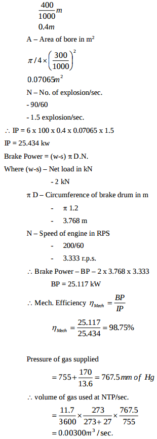
Question:During a trial on 4-stroke gas engine following observations were recorded: Bore = 300 mm ; Speed = 200 rpm Stroke = 400 mm ; Gas used = 11.7 m3/h Number of explosions/min = 90 Gauge pressure of gas = 170 mm of water Barometer reading = 755 mm of Hg Mean effective pressure = 6 bar Calorific value of gas used = 21500 KJ/kg at N.T.P. Net load on brake = 2 KN Brake drum diameter = 1.2 m Ambient temperature = 27°C Calculate: (i) mechanical efficiency (ii0 brake thermal efficiency.Answer: Indicated power – IP = PmepLAN Where Pmep – 6 bar – mean effective pressure - 6 x 100 kN/m2 L – Length of stroke in m
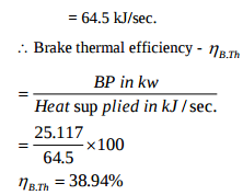
Assuming CV of gas used as 21,500 kj/m3 at NTP instead of 21,500 kJ/kg at NTH Heat supplied by fuel in kJ/sec. = 0.00300 x 21,500
|
| Q 3 a ) |
4 |
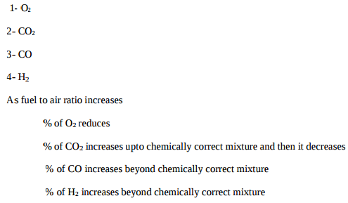
Question:The results of exhaust gas analysis for petrol engine running at full load and at constant speed are shown in Fig. No. 1. Label the exhaust gases (indicated by 1, 2, 3, 4). Which conclusion can be drawn from this figure.Answer:
|
| Q 3 b ) |
4 |
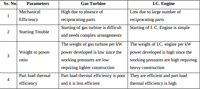
Question:State merits/demerits of gas turbine over T.C. engine with respect to following parameters: (i) mechanical efficiency (ii) starting trouble (iii) weight per power (iv) part load thermal efficiency.Answer:
|
| Q 3 c ) |
4 |
Question:List any four applications of refrigeration.Answer: i. To produce Ice in ICE Plant ii. To Store Vegetable or Domestic materials in Domestic Refrigerator. iii. To Transport Fish, Fruits etc. in Cold Storage. iv. To Cool Water in Water cooler. v. Processing of food products. vi. Processing of textiles, printing work, photographic materials etc. vii. Storage of ice, blood and medicines etc. viii. Preservation of photographic films , archeological documents etc ----------------------------------------------------------------------------------------------------- |
| Q 3 d ) |
4 |
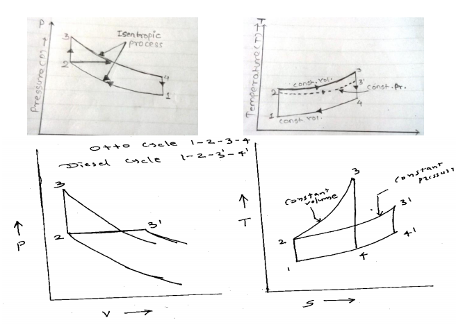
Question:Draw super imposed PV and TS diagrams of otto cycle, diesel cycle and dual cycle to compare their efficiencies under the following conditions: (i) for same compression ratio and heat rejection (ii) for same maximum pressure and temperature and heat rejection.Answer: Same compression ratio and same heat rejected heat rejection
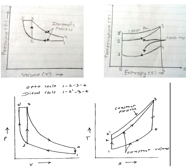
ii) For same maximum pressure and temperature and heat rejection
|
| Q 3 e ) |
4 |
Question:Draw P-V and T-S diagram for carnot cycle. Name the processes involved in it.Answer: PV and TS diagram of Carnot cycle
|
| Q 4a)(ii) |
4 |
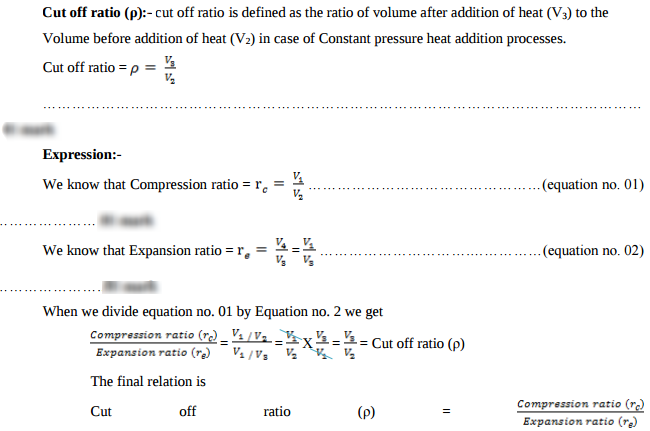
Question:Define cut off ratio. Express it in terms of compression ratio and expansion ratio.Answer:
|
| Q 4a)(iii) |
4 |
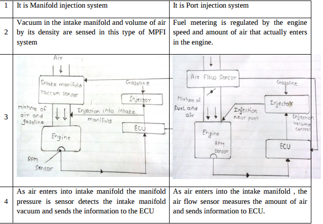
Question:Differentiate between L-MPFI system and D-MPFI system.Answer:
|
| Q 4a)(iv) |
4 |
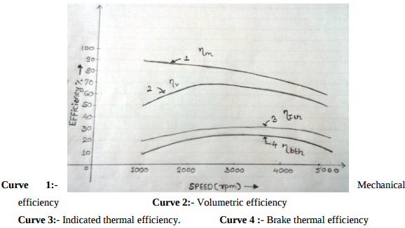
Question:Various efficiencies of 4-stroke petrol engine run at full throttle over its speed range are plotted in Fig. No. 2. Label different efficiency curves (indicated by 1, 2, 3, 4). Which conclusion can be drawn from this figure.Answer:
|
| Q 4a)(l) |
4 |
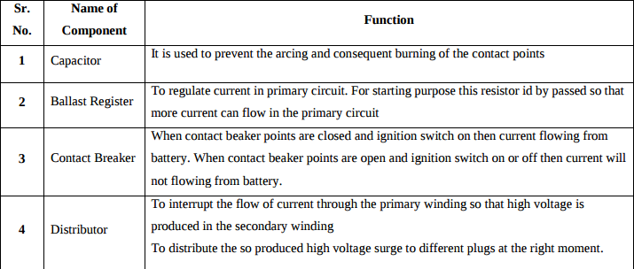
Question:State the functions of following components used in battery ignition system: 1) capacitor 2) ballast register 3) contact breaker 4) distributorAnswer: Function of Components used in battery ignition system
|
| Q 4b)(ii) |
6 |
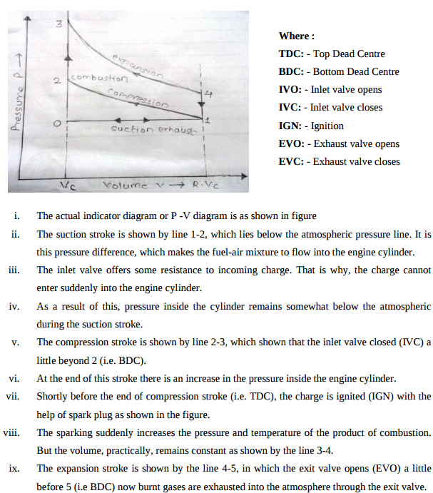
Question:Draw theoretical and actual P-V diagrams for S.I. engines and explain brieflyAnswer:
v. When piston is at TDC the air fuel mixture is come in clearance volume and theoretically it is assumed that spark is ignited in cylinder when piston is at TDC and volume during this combustion is constant (i.e. clearance volume) vi. At the end of combustion burnt gases exert pressure on piston and pushes the piston in downward direction. This process is represented by line 3-4, this process is also called as exhaust stroke. vii. At the end of this stroke exhaust valve is open and this burnt gases are expel out to atmosphere. viii. This exhaust stroke is represented by line 1-0 at atmospheric pressure.
x. The exhaust stroke is shown by the line 5-1, which lies above the atmosphere pressure line. It is pressure difference, which makes the burnt gases to flow out the engine cylinder. xi. The exit valve offers some resistance to the outgoing burnt gases. That is why, the burnt gases cannot escape suddenly from the atmospheric pressure line during the exhaust stroke. ----------------------------------------------------------------------------------------------------- |
| Q 4b)(l) |
6 |
Question:State the role of following lubricant additives: 1) zinc ditinophosphate 2) fatty acids 3) organic acids 4) ester 5) silicone polymers 6) butylene polymers.Answer: Role of following lubricant additives 1. Zinc ditinophosphate: - Zinc ditinophosphate serves as an anti – oxidant and anticorrosive additive. 2. Fatty acids: - This type of additives prevents rusting of ferrous engine parts during and form acidic moisture accumulation during cold engine operation. 3. Organic Acids: - This type of additives improves the detergent action of lubricating oil. 4. Ester: - To lower the pour point of lubricating oil. 5. Silicon polymers: - This additive serves as Antifoam Agent. 6. Butylene polymers: - This type of additives added in lubricating oil to increase their viscosity index. ----------------------------------------------------------------------------------------------------- |
| Q 5 a ) |
8 |
Question: Answer:
|
| Q 5 b ) |
8 |
Question:A single stage single acting air compressor delivers 0.6 kg of air per minute at 6.1 bar. The temperature and presure at the end of suction stroke are 28°C and 1.1 bar. The bore and stroke of the compressor are 100 mm and 150 mm respectively. The clearance is 3 % of the swept volume. Assuming index of compression and expansion as 1.25, find: (i) volumetric efficiency of compressor (ii) power required if mechanical efficiency is 85% (iii) speed of compressor in rpmAnswer:
|
| Q 5 c ) |
8 |
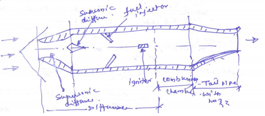
Question:Explain the construction and working of Ram jet with the help of neat labelled schematic diagram. State its limitations (any two).Answer:
Ramjet – it consist of inlet difference, combustion chamber and tail pipe (exist nozzle) Ramjet has no compressor as the entire compression depends upon compression. Function of supersonic & subsonic difference to convert the kinetic called the ram pressure. Working:- The air entering into ram jet with sup sonic speed is slowed down to sonic velocity in the air pressure is further increase in the sup sonic different increasing also the temperature of air. The diffuser section is designed to get correct ram effect its into decrees the velocity & increase pressure of in cooling air. The duel injected into combustion chamber is burned with help of igniter the high tress engine temperature garb are passed through the nozzle converting into pressure energy into kind energy. The high velocity gas leaving the nozzle provide required toward thrust to ramjet. Limitation 1. Ramjet engine be launched from an air plane flight. 2. Fuel consumption is too large. The fuel consumption lower decrees flight need. ----------------------------------------------------------------------------------------------------- |
| Q 6 a ) |
4 |
Question:Which is more effective way to increse the C.O.P. of refrigerator, to increase T2 keeping T1 constant or to decrease T1 keeping T2 constant? (T1 > T2). Give justification to your answer.Answer:
|
| Q 6 b ) |
4 |
Question:Define displacement of compressor for two stage compressor. Why is free air delivered less than displacement of compressor?Answer: Displacement is the product of piston displacement and working stroke per minute is bared on low pressure only and the amount air passing through the other cylinder for two stage compressor. When free air wave from low pressure cylinder to high pressure cylinder through intercooler there is reduction of volume of air because of perfect cooling so free air delivered is less than displacement of compressor. ( Pl check) ----------------------------------------------------------------------------------------------------- |
| Q 6 c ) |
4 |
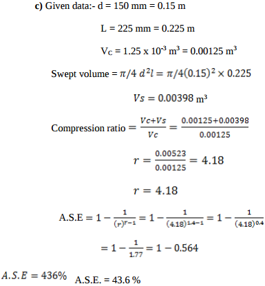
Question:An engine working on otto cycle has, d = 150 mm, L = 225 mm υc = 1.25 × 10⁻³ m3. Find air standard efficiency.Answer:
|
| Q 6 d ) |
4 |
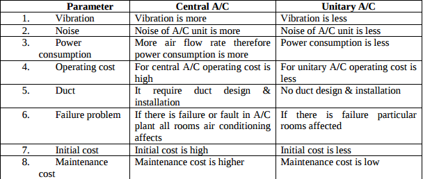
Question:Distinguish between central A/C and unitary A/C systems with respect to following parameters: (i) vibration (ii) noise (iii) power consumption (iv) operating cost (v) ducting (vi) failure problem (vii) initial cost (viii) maintenance costAnswer:
|
| Q 6 e ) |
4 |
Question:In gas turbine plants, Brayton cycle is more suitable than otto cycle, even though both cycles have equal thermal efficiency for same compression ratio. JustifyAnswer: In gas turbine plant – it works on brayton cycle where the heat added & heat rejected at constant pressure. It consists of compressor, combustion chamber & a turbine. The efficiency of Brayton cycle rotor cycle is same for but efficiency is of gas it temperature & pressure is increasing. High temperature & pressure require for ignition & fuel consumption for bray ton cycle. It is not possible in Oto cycle because the heat added & rejected at constant volume so bray ton cycle is most suitable than Otto cycle for gas turbine plant. ----------------------------------------------------------------------------------------------------- |

| Que.No | Marks | |
|---|---|---|
| Q 1a)(a) |
4 |
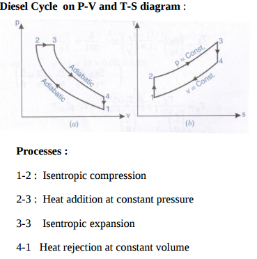
Question:Draw P-V and T-S diagram for Diesel cycle. Name the processes involved in it.Answer:
|
| Q 1a)(c) |
4 |
Question:Give the classification of air-compressorsAnswer: Classification of Air compressors: 1. According to principle: a. Reciprocating air compressors b. Rotary air compressors 2. According to the capacity a. Low capacity air compressors b. Medium capacity air compressors c. High capacity air compressors 3. According to pressure limits a. Low pressure air compressors b. Medium pressure air compressors c. High pressure air compressors 4. According to method of connection a. Direct drive air compressors b. Belt drive air compressors c. Chain drive air compressors ----------------------------------------------------------------------------------------------------- |
| Q 1a)(d) |
4 |
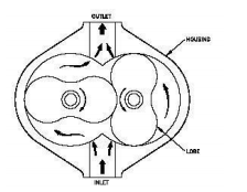
Question:Explain with neat sketch working principle of Lobe compressorAnswer: Rotary Lobe type Air Compressor has two mating lobe-type rotors mounted in a case. The lobes are gear driven at close clearance, but without metal-to-metal contact. The suction to the unit is located where the cavity made by the lobes is largest. As the lobes rotate, the cavity size is reduced, causing compression of the vapor(air) within. The compression continues until the discharge port is reached, at which point the vapor exits the compressor at a higher pressure.
|
| Q 1b)(a) |
6 |
Question:State different methods of determining frictional power of I.C. engine and explain any one methodAnswer: Methods to determine the frictional power of I.C. engine are` 1. Willan’s line method 2. Morse test 3. Motoring test 4. Difference between i.p. and b.p. Explanation of any one method ----------------------------------------------------------------------------------------------------- |
| Q 1b)(b) |
6 |
Question:Explain with neat sketch working principle of any one type of catalytic converter.Answer:
|
| Q 1b)(i) |
4 |
Question:Define : i) Brake thermal efficiency ii) BSFC related to I.C. Engine.Answer: i) Brake thermal efficiency – It is defined as the ratio of heat equivalent to brake power per unit time to the heat supplied to the engine per unit time Brake thermal efficiency = B.P./ mf x C.V. ii) BSFC – It is the mass of fuel required to develop 1 kW brake power for a period of one hour. It is inversely proportional to the brake thermal efficiency. BSFC = Mass of fuel consumed in kg/hr / Brake power in kW ----------------------------------------------------------------------------------------------------- |
| Q 2 a ) |
8 |
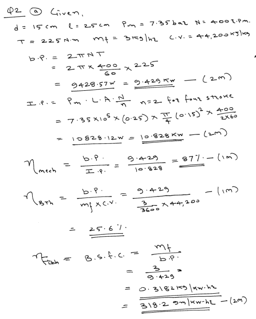
Question:Following observations were recorded during a trial on single cylinder four stroke oil engine : Cylinder bore = 15 cm Length of stroke = 25 cm Mean effective pressure = 7.35 bar Engine speed = 400 rpm Brake torque = 225 N.m. Fuel consumption = 3 kg/hr Calorific value of fuel = 44200 kJ/kg. Determine : i) Mechanical efficiency ii) Brake thermal efficiency iii) Brake specific fuel consumption.Answer:
|
| Q 2 b ) |
8 |
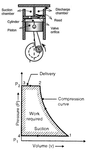
Question:Explain construction and working of single stage reciprocating air compressor with neat sketch. Also represent it on P-V diagram.Answer: In single stage reciprocating air compressor, the entire compression is carried out in a single cylinder. The opening & closing of a simple check valve (plate or spring valve) depends upon the difference in pressure, if mechanically operated valves are used for suction & discharge then their functioning is controlled by cams. The weight of air in the cylinder will be zero when the piston is at top dead centre. At this position, you have to neglect clearance volume. When piston starts moving downwards, the pressure inside the cylinder falls below atmospheric pressure& suction valve/inlet valve opens. The air is drawn into the cylinder through a suction filter element. This operation is known as suction stroke. When the piston moves upwards, compresses the air in cylinder & inlet valve closes when the pressure reaches atmospheric pressure. Further compression follows as the piston moves towards the top of its stroke. Until when the pressure in the cylinder exceeds that in the receiver. This is compression stroke of a compressor. At the end of this stroke discharge/delivery valve opens & air is delivered to a receiver
----------------------------------------------------------------------------------------------------- |
| Q 2 c ) |
8 |
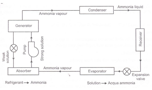
Question:Explain working principle of simple vapour absorption refrigeration system. Represent it on the block diagram.Answer: Working of Simple Vapor absorption system: A Simple Vapor absorption system consists of evaporator, absorber, generator, condenser, expansion valve, pump & reducing valve. In this system ammonia is used as refrigerant and solution is used is aqua ammonia. Strong solution of aqua ammonia contains as much as ammonia as it can and weak solution contains less ammonia. The compressor of vapor compressor system is replaced by an absorber, generator, reducing valve and pump. The heat flow in the system at generator, and work is supplied to pump. Ammonia vapors coming out of evaporator are drawn in absorber. The weak solution containing very little ammonia is spread in absorber. The weak solution absorbs ammonia and gets converted into strong solution. This strong solution from absorber is pumped into generator. The addition of heat liberates ammonia vapor and solution gets converted into weak solution. The released vapor is passed to condenser and weak solution to absorber through a reducing valve. Thus, the function of a compressor is done by absorber, a generator, pump and reducing valve. The simple vapor compressor system is used where there is scarcity of Electricity and it is very useful at partial and full load.
|
| Q 3 a ) |
4 |
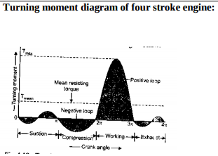
Question:Draw turning moment diagram for four stroke petrol engine and explain it in brief.Answer:
During suction stroke, negative loop is formed as pressure inside engine cylinder is less than atmospheric pressure. During compression stroke, work is done on gases therefore higher negative loop is formed. During expansion or power stroke, fuel burn & gases expand therefore large positive loop is formed & during this stroke we get work output. During exhaust stroke, work is done on the gas to expel it out of cylinder, hence negative loop is formed. ----------------------------------------------------------------------------------------------------- |
| Q 3 b ) |
4 |
Question:What is supercharging ? State advantages of supercharging.Answer: Superchargers are pressure boosting devices (compressors) which increase the pressure of the air before inletting it get into cylinder of the internal combustion engine, and the process of increasing the pressure OR forcing more air to get into engine is called as supercharging. This gives each intake cycle of the engine more oxygen, letting it burn more fuel and do more work, thus increasing power. Advantages 1. Higher power output. 2. Reduced smoke from exhaust gases. The extra air pushed into cylinder, helps the air to complete combust leading to lesser smoke generation. 3. Quicker acceleration of vehicle. Supercharger starts working as soon as the engine starts running. This way the engine gets a boost even at the beginning leading to quicker acceleration. 4. Cheaper than turbocharger. ----------------------------------------------------------------------------------------------------- |
| Q 3 c ) |
4 |
Question:State effects of pollutants in exhaust gases of petrol engine.Answer: The major air pollutants emitted by petrol engines are CO2, CO, HC, NOx, SO2, smoke & lead vapour. Effect of CO: Carbon monoxide combines with hemoglobin forming carboy hemoglobin, which reduces oxygen carrying capacity of blood. 1. This leads to laziness, exhaustion of body & headache. 2. Prolong exposure can even leads to death. 3. It also affects cardiovascular system, thereby causing heart problem Effect of CO2: Causes respiratory disorder & suffocation. Effect of HC: 1. It has effect like reduced visibility, eye irritation, peculiar odour & damage to vegetation & acceleration the cracking of rubber products. 2. It induce cancer, affect DNA & cell growth are know a carcinogens. Effect of SO2: It is toxic & corrosive gas, human respiratory track of animals, plants & crops. ----------------------------------------------------------------------------------------------------- |
| Q 3 d ) |
4 |
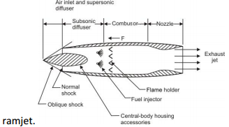
Question:Explain with neat sketch working principle of Ram jet engineAnswer: Ramjet has no compressor as the entire compression depends upon compression. Function of supersonic & subsonic difference to convert the kinetic called the ram pressure. Working:- The air entering into ram jet with supersonic speed is slowed down to sonic velocity in the supersonic diffuser ,increasing air pressure. The air pressure is further increase in the subsonic diffuser increasing also the temperature of air. The diffuser section is designed to get correct ram effect. it’s job is to decrease the velocity & increase pressure of incoming air. The fuel injected into combustion chamber is burned with help of flame igniter. The high pressure and high temperature gases are passed through the nozzle converting into pressure energy into kinetic energy. The high velocity gas leaving the nozzle provide required toward thrust to.
|
| Q 3 e ) |
4 |
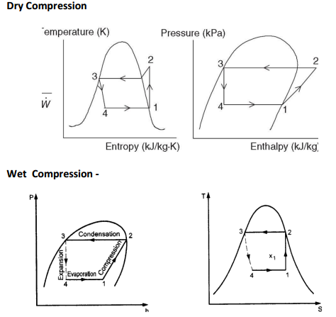
Question:Represent wet compression and dry compression on T-S and P-H diagram and name all processes involved in itAnswer:
|
| Q 4a)(a) |
4 |
Question:What are the effects of detonation in I.C. engine ?Answer: Effects of detonation (1) Noise – As intensity of detonation increases, the sound intensity increases & it is harmful. (2) Mechanical damage – shock waves are so violent that it may cause mechanical damage like breaking of piston. It increases the rate of wear erosion of piston. (3) Pre-ignition – Due to local overheating of spark plug & this pre-ignition increases detonation. (4) Power output & efficiency decreases - Power output & thermal efficiency decreases due to abnormal combustion. (5) Increase in heat transfer – Temperature of cylinder in detonating engine is higher than in non – detonating engine, hence increases the heat transfer. (6) Carbon deposits- Detonation results in increased carbon deposits ----------------------------------------------------------------------------------------------------- |
| Q 4a)(b) |
4 |
Question:Define : i) Mechanical efficiency ii) Volumetric efficiency related to I.C. engine.Answer: i) Mechanical Efficiency- It is the ratio of the power available at the engine crankshaft (bp) to the power developed in the engine cylinder (ip). ii) Volumetric efficiency :- It is the ratio of the actual volume of the charge admitted into the cylinder to the swept volume of the piston . ----------------------------------------------------------------------------------------------------- |
| Q 4a)(c) |
4 |
Question:State advantages of closed cycle gas turbine.Answer: Advantages of closed cycle gas turbine: (i) It has higher thermal efficiency for the same minimum and maximum temperature limits and for the same pressure ratio. (ii) Since the heating is external, any kind of fuel even solid fuel having low calorific value may be used. (iii) There is no corrosion due to circulation of combustion product. (iv) As the system is a closed one there is no loss of the working fluid. (v) The size of the turbine will be smaller compared to an open cycle gas turbine of the same output. (vi) The regulation is more simple. (vii) The heat transmission coefficient in the exchanger is better due to the increase in suction pressure. (viii) Loss due to fluid friction is less due to higher Reynolds number. ----------------------------------------------------------------------------------------------------- |
| Q 4b)(a) |
6 |
Question:Explain with neat sketch working principle of four stroke petrol engine.Answer:
|
| Q 4b)(b) |
6 |
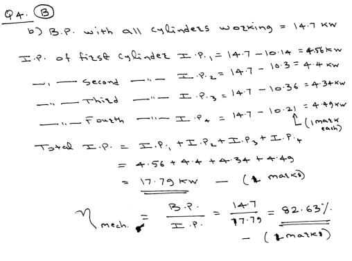
Question:The following data is collected during a trial of four stroke four cylinder petrol engine. B.P. with all cylinders working = 14.7 kW B.P. with cylinder no. 1 cut off = 10.14 kW B.P. with cylinder no. 2 cut off = 10.3 kW B.P. with cylinder no. 3 cut off = 10.36 kW B.P. with cylinder no. 4 cut off = 10.21 kW Find mechanical efficiency of engine.Answer:
|
| Q 4 d ) |
4 |
Question:State advantages of jet propulsion over other systems.Answer: Advantages of jet propulsion – 1. Higher mechanical efficiency due to absence of reciprocating parts. 2. The weight of gas turbine per kW power developed is low since the working pressures are low requiring lighter construction. 3. Can produce much more power at much higher altitudes where drag is less so higher speeds are possible and they are more efficient. 4. Reliability is one of the elements of success for jet engines. They only have a couple of moving parts and almost no vibration. ----------------------------------------------------------------------------------------------------- |
| Q 5a)(i) |
8 |
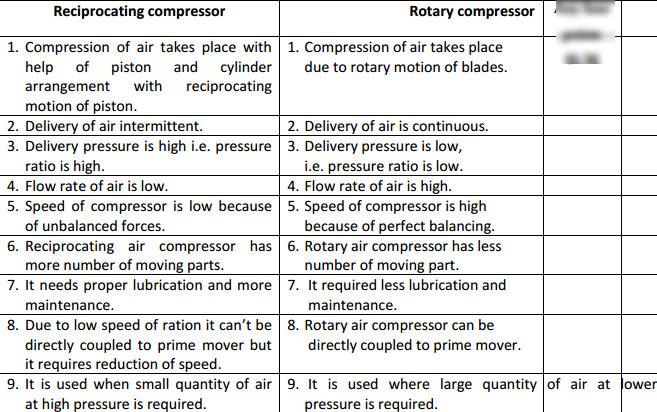
Question:Compare reciprocating and rotary compressors (any four).Answer:
|
| Q 5a)(ii) |
8 |
Question:Write any four applications of compressed air.Answer: Following are the applications of compressed air:- 1) To drive air motors in coal mines. 2) To inject fuel in air injection diesel engines. 3) To operate pneumatic drills, hammers, hoists, sand blasters. 4) For cleaning purposes. 5) To cool large buildings. 6) In the processing of food and farm maintenance. 7) For spray painting in paint industry. 8) In automobile & railway braking systems. 9) To operate air tools like air guns. 10) To hold & index cutting tools on machines like milling. ----------------------------------------------------------------------------------------------------- |
| Q 5 b ) |
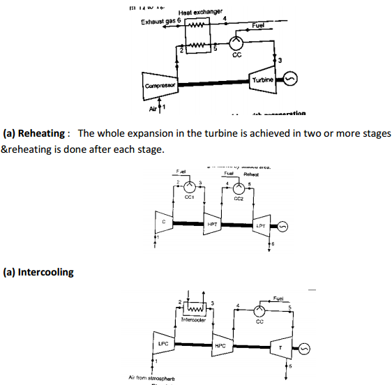
8 |
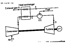
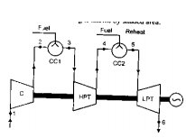
Question:List the methods to improve thermal efficiency of gas turbine and explain any one of them in detailAnswer: Methods to improve thermal efficiency of gas turbine 1) Regeneration – This is done by preheating the compressed air before entering to the combustion chamber with the turbine exhaust in a heat exchanger, thus saving fuel consumption.
2) Reheating : The whole expansion in the turbine is achieved in two or more stages & reheating is done after each stage. That increase in work done.
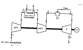
3) Intercooling –The compression is performed in two or more stages. But between two stage there is intercooler where cooling takes place at constant pressure.To increase net work of gas turbine by saving some compression work.
----------------------------------------------------------------------------------------------------- |
| Q 5 c ) |
8 |
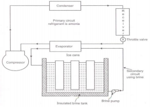
Question:Explain with neat sketch working principle of Ice plant.Answer: Working of Ice plant: The main cycle used for ice plant is vapor compression cycle with ammonia as the refrigerant in primary circuit and brine solution in secondary circuit. Brine solution takes heat from water in secondary circuit and delivers the heat to ammonia in primary circuit. Thus, the indirect method of cooling is used in ice plant. In secondary circuit brine is cooled in evaporator and then it is circulated around the can which contains water. The heat is extracted from the water in the can and is given to the brine. The brine is contentiously circulated around the can with the help of brine pump till entire water in the can is converted into ice at -6 0 C. Ammonia vapor coming out of evaporator is compressed to high pressure and then these vapors are condensed in the condenser. High pressure liquid ammonia is collected in the receiver and it is passed through the expansion valve to reduce its pressure and temperature as per requirement. The throttle liquid ammonia at low temperature & low pressure enters in evaporator, which are the coils dipped in brine tank. The liquid ammonia absorbs heat from brine and gets converted into vapors, which are drawn by suction line of compressor.
|
| Q 6 a ) |
4 |
Question:State any four types of sensors used in I.C. engine.Answer: Following sensors are used in ECU: A permanent magnet inductive signal generator is mounted in close proximity to the flywheel, where it radiates a magnetic field. As the flywheel spins and the pins are rotated in the magnetic field, an alternating (AC) waveform is delivered to the ECM to indicate speed of rotation. Air Flow Sensor (AFS): The AFS is normally located between the air filter and the throttle body. As air flows through the sensor, it deflects a vane (flap) which wipes a potentiometer resistance track and so varies the resistance of the track and generates a variable voltage signal. Manifold absolute pressure (MAP) sensor: The MAP sensor measures the manifold vacuum or pressure, and uses a transducer to convert the signal to an electrical signal which is returned to the ECM. The unit may be designed as an independent sensor that is located in the engine compartment or integral with the ECM. Coolant temperature sensor (CTS): The CTS is a two-wire thermistor that measures the coolant temperature. The CTS is immersed in the engine coolant, and contains a variable resistor that usually operates on the NTC principle. Throttle Position Sensor (TPS): TPS is provided to inform the ECM of idle position, deceleration, rate of acceleration and wide-open throttle (WOT) conditions. The TPS is a potentiometer which varies the resistance and voltage of the signal returned to the ECM. Oxygen sensor (OS): An oxygen sensor is a ceramic device 'placed in the exhaust manifold on the engine side of the catalytic converter. The oxygen sensor returns a signal to the ECM, which can almost instantaneously (within 50 ms) adjust the injection duration ----------------------------------------------------------------------------------------------------- |
| Q 6 b ) |
4 |
Question:Define : i) Isothermal efficiency. ii) Volumetric efficiency with respect to air compression.Answer: i) Isothermal efficiency – It is defined as the ratio of isothermal power to the indicated or actual power. Isothermal efficiency = Isothermal power / Indicated power.
ii) Volumetric efficiency – It is the ratio of actual volume of the free air delivered at standard atmospheric condition at discharge in one delivery stroke to the swept volume by the piston during the stroke. ----------------------------------------------------------------------------------------------------- |
| Q 6 c ) |
4 |
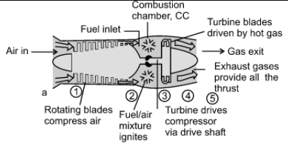
Question:Explain with neat sketch working principle of turbo jet engine.Answer: Working principle of Turbojet: shows the schematic of turbojet engine. It has a diffuser section at inlet for realizing some compression of air passing through this section. Due to this air reaching compressor section has pressure more than ambient pressure. This action of partly compressing air by passing it through diffuser section is called “ramming action” or “ram effect”. Subsequently compressor section compresses air which is fed to combustion chamber and fuel is added to it for causing combustion. Combustion products available at high pressure and temperature are then passed through turbine and expanded there. Thus, turbine yields positive work which is used for driving compressor. Expanding gases leaving turbine are passed through exit nozzle where it is further expanded and results in high velocity jet at exit. This high velocity jet leaving nozzle is responsible for getting desired thrust for propulsion.
|
| Q 6 d ) |
4 |
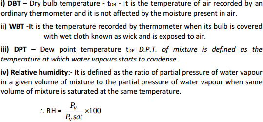
Question:Define : i) DBT ii) WBT iii) DPT iv) Relative humidity.Answer:
|
| Q 6 e ) |
4 |
Question:Give the classification of air conditioning systems.Answer: Air conditioning systems are classified as 1) Classification as to major function- i) Comfort air-conditioning - air conditioning in hotels, homes, offices etc. ii) Commercial air-conditioning- air conditioning for malls, super market etc iii) Industrial air-conditioning – air conditioning for processing, laboratories etc 2) Classification as to season of the year- i) Summer air-conditioning - These system control all the four atmospheric conditions for summer comfort. ii) Winter air-conditioning – This system is designed for comfort in winter. iii) Year round air-conditioning – These system consists of heating and cooling equipments with automatic control to produce comfortable condition throughout the year 3)According to equipment arrangement-Unitary and Central air conditioning. ----------------------------------------------------------------------------------------------------- |
Pages
- « first
- ‹ previous
- 1
- 2
- 3
- 4