Q.1. Explain the working of gear pum
Ans :Gear pumps are positive displacement pumps. A partial vacuum is created as the internal gears go through their cycle, and oil is forced up into the pump due to atmospheric pressure on the oil surface. This oil is then carried to the delivery port by teeth and finally forced out to the actuator.
Constructional details:
As shown in the diagram besides the pump
consists of two intermeshing gears (machined to close tolerance)
which are situated in four bearing blocks with axially lobed seals,
housing with front and back cover. The input shaft rests on the
casing fixed in front cover and sealed with seal ring. The material
from which pump housing is made is rolled aluminum of extremely high
endurance or cast iron. The two covers are made up of gray cast iron.
The gears have 12- teeth, which reduces the variation of output flow
rate and noise level respectively.
Operation :
When the pump is started working liquid
is trapped in the gaps between the gear teeth, and is propelled along
the inside of the pump from the suction (inlet) port to the pressure
(outlet) port. The partial vacuum needed to produce suction in the
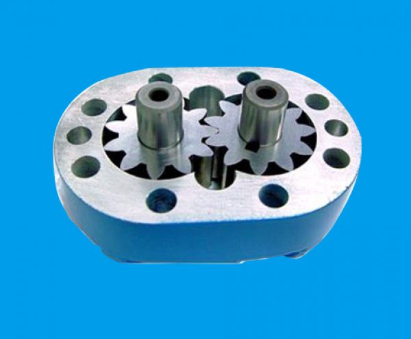
suction chamber is generated when the teeth take away liquid along with them from suction chamber; thus, reduction in the volume of suction chamber creates suction. The suction and delivery sides are constantly sealed due to continuous meshing of gears.{Actual gear pump image For Understanding}
Q.2. Explain the working of EXTERNAL gear pump.
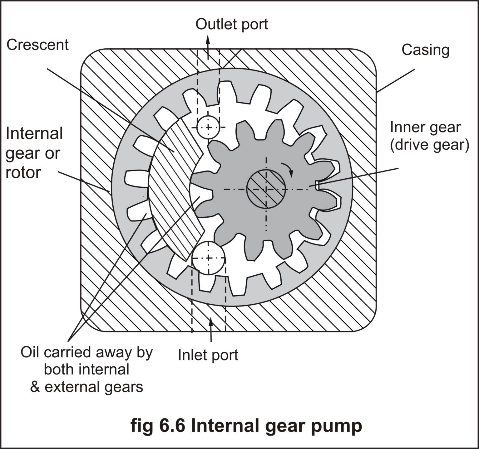
It consists of one external and one internal meshing gear pair. External gear is connected to electric motor and hence is driving gear. Internal gear or ring gear is driven gear which rotates in same direction as that of external gear. Between two gear a spacer called ‘crescent’ is located which is a stationary pieces connected to housing. Inlet and outlet ports are located in end plates. External gear (driving gear) drives theinternal gear (Ring Gear). Portion where teeth start meshing, a tight seal is created near port the vacuum is created due to quickun-meshing and oil enters from oil tank through inlet port. Oil istrapped between the internal and external gear teeth on both sides of crescent (spacer) and is then carried from inlet to outlet port. Meshing of gear near outlet port reduces the volume or gap and oil
gets pressurized. These pumps make very less noise.
{Actual internal gearpump image for Understanding }
Q.3. Explain the working of vane pump.
Ans :Vane type pumps operate on the principle of increasing and diminishing volume. The oil from suctionport is confined into a chamber comprising sliding vanes and as the rotor proceeds the volume of this chamber goes on reducing resulting pressure in the fluid and in last the pressurized fluid is discharged (forced) into delivery chamber.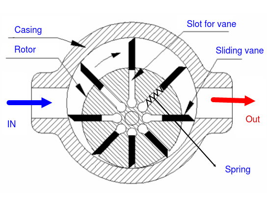
As shown in fig. in its simplest version, it consists of a rotor in which vanes are held in a series of slots around the rotor. The rotor is off set within the housing, and the vanes are constrained by the cam ring as they cross inlet and outlet ports. Operation :As the rotor rotates in clockwise direction, the area between the two vanes is sealed as the vane uncovers suction port, this creates partial vacuum in suction chamber and results in suction of hydraulic fluid into suction chamber. Further, the fluid confined between two vanes is carried away to the outlet chamber, forcing the fluid into the delivery port.
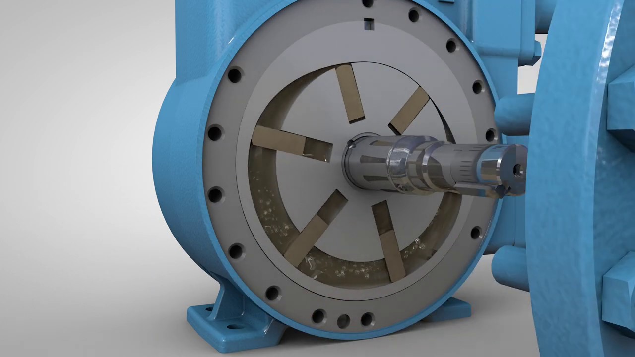
{Actual Vane Pump for understanding }
Q.4. Explain the working of Screw pump. State its advantages and limitations
Ans : These pumps use screws to transmit fluid from suction to delivery port. The fluid is carried foreword to the discharge by the screw, very much similar a nut moves along a screw. The helical grooves on the screws serves as the path for fluid from suction chamber to delivery chamber.
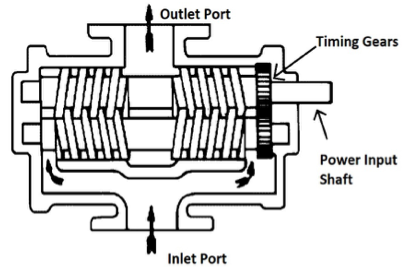
Constructional
details : The figure below illustrates the construction
details of a screw type pump. The screws are hardened and precision
ground, which are enclosed in a closely machined casing. Each of the
two screws have half part right hand threading and other half part
left hand threading. These screws mesh to from a fluid tight seal
between the screws and the screw and casing. Out of two screws, one
is connected to power source and another is driven through gears.
Operation
As the screw rotates it draws oil from
the suction chamber, enfold it into the helical grooves. As the screw
further rotates the fluid gets transferred along the screw and
finally forced into delivery chamber. Thus oil is sucked continuously
from four points and finally discharged into delivery chamber.
Advantages and limitations of screw type
pumps
Advantages :
1) They provide continuous (non -
pulsating) flow.
2) Few moving parts and rolling action of
rotors make them quite in operation and more reliable.
Limitations :
1) Screw pumps are available with
operating pressure upto 200 bar.
2) Fixed displacement :Screw type pumps
are fixed displacement pumps; this characteristic limits their
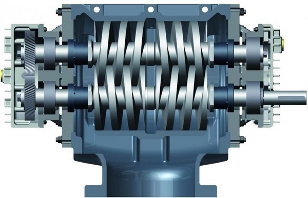
application where variable displacement is required. {Actual hydraulic screw pump for
understanding }
Q.5. Explain the working of radial type piston pump.
Ans :As shown in the diagram a typical radial piston pump has a fixed casing incorporating suction and delivery ports in it.
Inside the fixed casing there is a rotating piston block (which
carries pistons in it), and at the center there is a fixed eccentric
cam, whose center and the center of rotation of the block are offset
by an amount equal to 'e' (as shown).Operation :As the piston block rotates in
clockwise direction, the eccentricity causes the piston on the
suction side to move inwards, towards center (due to spring force)
and pistons on delivery side to move outwards (due to reducing
eccentricity). This motion of pistons causes suction and delivery of
the fluid. Radial piston pumps are also available in constructions,
which provide variable displacement. In such designs, the
eccentricity
of the pump is changed manually or hydraulically with load dependent sensing.
The flow direction of the pumps is
determined by the direction of rotation and by adjusting range of the
stroke ring, displacement can also be varied. {Actual Radial Piston Pump for
understanding purpose is shown}
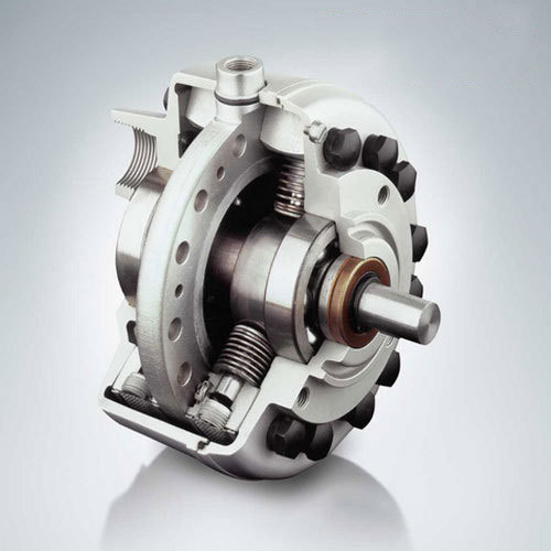
Q.6. Explain the working of Swash Plate type Axial piston Pump.
Ans :Swash plate type axial piston pumps, as shown in diagram consists of rotating cylinder barrel, which consists piston arranged on it axially. The piston ends are connected to an inclined swash plate.
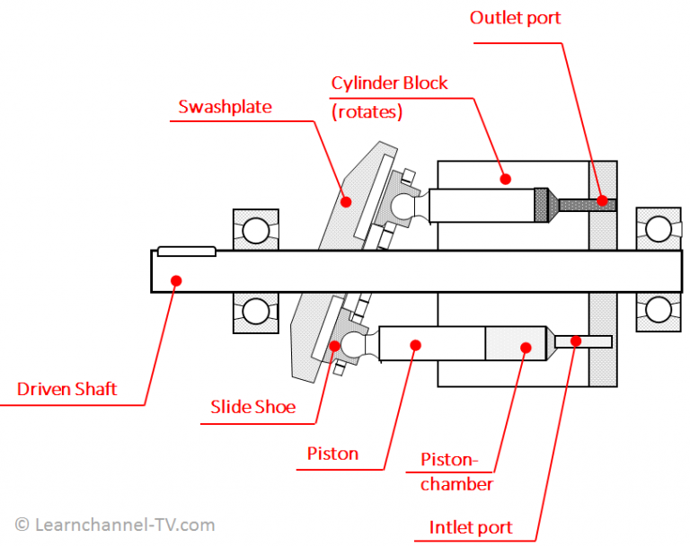
The direction of piston movement (forward
or backward i.e. suction or delivery) is decided by its peripheral
position on swash plate. The rotating piston travels along an
elliptical line on the stationary swash plate. The friction between
piston ends and stationary swash plate is kept intact with swash
plate by retaining ring. The suction and delivery chambers are shown
in cross-section.
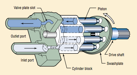
Operation :
As the shaft rotates, it imparts motion
to pistons, but since piston ends are connected to an inclined swash
plate the pistons start reciprocating (with a stroke length as
determined by inclination of swash plate ).
The reciprocating motion of piston causes suction and delivery of
fluid as the respective pistons uncover the suction and delivery
ports. The delivery (discharge) of this type of pump can be varied or
even reversed by changing the swash plate angle.
Following are the various positions
indicating maximum forward flow, neutral position (no flow) and
maximum reverse flow (suction and delivery ports get interchanged).
{Actual Swash Plate type Pump for
Understanding }
Q.7.What is swash plate? What is its use? What will happen if we change the angle of swash plate? Explain with sketch.
Swash Plate – It’s an inclined
plate in axial piston pump on which all pistons are connected through
piston rod. This swash plate is usually inclined.
Use – It is helps to
reciprocate the piston of axial piston pump while the cylinder block
is rotating Working: Motor drives the shaft, which in turn rotates
the entire cylinder block. The pistons are connected to inclined
swash plate through piston rod. Now since swash plate is inclined and
block is rotating, the piston reciprocates inside the barrel. The
reciprocating motion of piston causes suction and delivery of fluid
through inlet and outlet ports which come infront of outlet of
piston.
If we change the angle of swash plate
i.e. θ if ,
a) θ = 0 then no flow of oil, because
pistons are at same level. When θ = 0 swash plate is vertical. No
reciprocation of piston, hence no flow.
b) θ = max or +ve, then x will be stroke
length which is maximum and there will be maximum forward flow.
c)
θ = -ve, then ‘x’ i.e. stroke length will be maximum in reverse
direction and hence there will be reverse flow. By changing the swash
plate angle we can vary the stroke length of the piston. and also
output flow can be changed
Q.8. Explain the working of bent axis type piston Pump.
Ans :As shown in the diagram, the pump consists of a cylinder barrel, which carries pistons arranged on it axially. The piston ends are connected to a flange by ball joints.
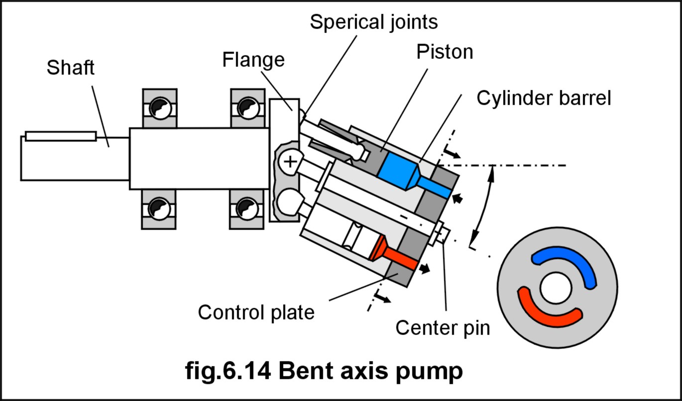
The cylinder barrel is inclined at an
angle with the axis of rotation of flange. Suction and pressure sides aresplit by control slots drilled in the control plate. As the shaftrotates the flange, the flange imparts rotary motion to cylinder barrel, which is turn rotates the pistons. Due to the inclination of barrel, the pistons in addition to rotating with cylindrical barrel start reciprocating. The reciprocating motion of piston causes suction and delivery of fluid as the respective pistons uncover the suction and delivery ports. Various designs of bent axis pump exist,where the cylinder barrel drive is obtained by bevel gear or cordon
joint.
- Log in to post comments