Brakes Clutches Design Key points to remember :
Brakes clutches are very important components in a mechanical system
- Brakes Clutches Design :A brake is a mechanical device which is used to absorb the energy possessed by a moving system by means of friction. The main function of brake is to retard or stop the motion of a moving system. The brake is also used to hold the parts at its position, this function is applicable in hoists and lifts. Mostly the kinetic energy absorbed by brake is converted into heat and dissipated to surroundings.
- Brakes are of mechanical type , Hydraulic and pneumatic type , electric type.
- Mechanical type brakes are mainly classified as
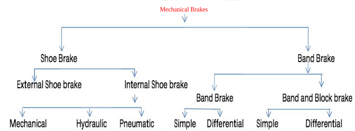
- Internal exapanding shoe brake is most widely used in automobile. Block brakes are used in locomotives. Band brakes are mostly used in industrial machines.
- Disk brakes have two pads on either side of disk, which when actuated try to hold the disk, thus the braking action of disk brake is more quick.
Clutches :
- Clutch is mechanical device which is used to connect or disconnect the output shaft to input shaft whenever required. In othre words clutch is a temporary coupling between two shafts which can be easily disconnected by simple operating a lever. The need of a clutch arised mainly due to automobiles where there is need of disconnection between input(engine) and output shaft(wheels) during the gear shifting.
- Clutches are classified as,

- Positive contact clutches transmit power by interlocking of jaws,friction clutches by friction between contacting surfaces,electromagnetic clutches by magnetic field and fluid clutches by oil pressure.
- Two or more friction surfaces are pressed together with a nomal force to create the frictional torque. The springs provide the necessary axial force for the engagement.
- Friction clutches mainly have the friction linings between mating surfaces which get engaged or disengaged . The torque is transmitted by friction lining.
- Torque transmission capacity of clutch is determined by two approaches (theories). One is uniform pressure theory and another is uniform wear theory. In uniform pressure theory it is assumed that the pressure on friction lining is same from inner radius to outer radius, whereas in uniform wear theory it is assumed that the pressure is more at inner edge of lining and goes on reducing towards outer lining.
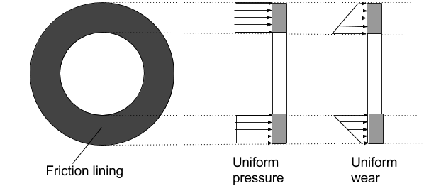
- When the clutch is new and just put into operation the assumption of uniform pressure holds good, but it can be observed that when the clutch rubs against pressure plate the outer edge rubs more than inner edge, because of radius difference. As a result the outer edge wears more rapidly than inner one, and hence the pressure distribution gets altered. Now the assumption of uniform wear theory holds good. So while designing clutch generally uniform wear theory is given preference over uniform pressure theory.
Theory Questions and Answers on Brakes and Clutches
BRAKES :
Q.1.) What do you mean self-locking and self energizing block brakes ?
Ans : The equation for the force required to operate the block brake,
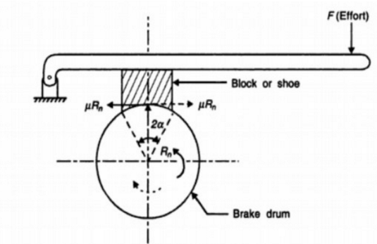
Where P= Braking force applied at the end of a lever l, Rn= Normal reaction,x= distance of brake,drum from centre of fulcrum,u= coefficient of friction
Here arise three situations depending upon the variables x,u and a.
- Situation I : In above equation if
, the effort P became zero, means no effort is required to apply brakes and hence the brake is called self locking. This condition is not desirable in brakes.Some braking force must be applied to the brake otherwise the brake will not be in control of operator.
- Situation II : In above equation if
, in this case the the fricition generated moment helps the braking moment , such condition is called the self energizing brake. In this situation less braking force is required. This condition is desirable in brakes. Brakes must be designed to take full advantage of this self energizing effect to reduce the operator force required.
- Situation III ; Under this situation in above equation if
, the effort force P becomes negative, Means the brake will remain loacked even no force is applied on the brake. This is dangerous condition and makes the brake completely out of control of the operator. In all circumstances this situation must be avoided by designer.
Q.2.) State the different types of brakes with at least one practical application of each type ?
Ans
Q.3.) What are the advantages of pivotes shoe brake over fixed shoe brake ?
Ans
Q.4.) With a neat sketch explain internal expanding shoe brake ? State its advantages? where it is used?
Ans
Q.5.) With a neat labled diagram explain Band Brake? State its advantages and limitations? Where band brakes are used.
Ans
Q.6.) Expalin with sketch working of disk brake ? State its advantages over drum brake.
Ans
CLUTCH :
Q.7.) Classify Friction clutches ? State one application of each type of clutch
Ans
Q.8.) What are the advantages of single plate clutch over multiplate clutch ? Why multiplate clutch is preffered in two wheeler bikes.
Ans
Q.9.) Why Uniform wear theory is preffered over uniform pressure theory in clutches ?
Ans
Q.10.) Explain with sketch working of single plate clutch?
Ans
Q.11.) Explain with sketch working of single plate clutch?
Ans
Q.12.) Explain with sketch working of Multiple plate clutch?
Ans
Q.13.) Explain with sketch working of cone clutch?
Ans
Q.14.) Explain with sketch working of Centrifugal clutch?
Ans
Q.11.) Explain with sketch working of Diaphragm clutch?
Ans
Q.11.) Explain with sketch working of single plate clutch?
Ans
Numerical Problems on Brakes Clutches Design Different types of brakes
A) Energy analysis of Brakes
1) A four-wheeler has a total mass of 900 kg. The moment of inertia of each wheel is about a transverse axis through its centre of gravity is 0.5 kg-m 2 . The rolling radius of the wheel is 0.35 m. The rotating and reciprocating parts of the engine and the transmission system are equivalent to a moment of inertia of 2.2 kg-m 2 rotating at 5 times the speed of the road wheel speed. The car is travelling at a speed of 80 km/hr on a plane road. When the brakes are applied, the car decelerates at 0.4 g. There are brake on all four wheels.
Determine :
(i) The energy absorbed by brake.
(ii) The torque capacity of the brake.
2) A four wheeled automobile car has total mass of 1000 kg. The moment of inertia of each wheel about transverse is 0.5 kg-m2. The rotating and reciprocating parts of engine and transmission system are equivalent to MI of 2.5 kg-m2, which rotate at 5 times the speed of road wheel.The wheel has rolling radious of 350 mm. If the car is travelling at a speed of 100 KMPH on a levelled plane road, the brakes are applied which decelerates at 0.5 g, by applying all four brakes calculate,
- Energy absorbed by each brake
- Torque capacity of each brake.
B) Block Brake
1) A block brake with a short shoe is shown in Fig. below. It is designed so that the product p×V is limited to 2. Where p= normal pressure between friction lining and the brake drum. V= peripheral velocity of brake drum.
The coefficient of friction between the brake drum and the friction lining is 0.2. The cable drum is connected to the brake drum by means of a pair of spur gears. The brakedrum rotates four times as fast as the cable drum. The Permissible Intensity of pressure on friction lining is 1MPa.

Calculate:
i) The magnitude of brake shoe force F
ii) The area of friction lining.
iii) The uniform velocity at which the mass can be lowered. What happens at higher speed.
2) A double block brake with an identical pivoted shoes is to be used for braking torque capacity of 1 kN/m the diameter of brake drum is 400 mm & angle of wrap for each shoe is 1200 . The coefficient of friction is 0.3 and the permissible intensity of pressure is 0.8 N/mm2 . The pivot of each shoe is located in such a way that moment of frictional force on the shoe about pivot is zero. Calculate,
i) Distance of pivot from the axis of brake drum.
ii) The width of friction lining parallel to axis of drum.
3) A pivoted double block brake has two shoes each of which subtend an angle of 120° at the centre of the brake drum. The diameter of the brake drum is 450 mm. and the width of the friction lining is 75 mm. The coefficient of friction is 0.2 and the maximum intensity of pressure between the lining and the brake drum is 0.5 N/mm 2 . The pivot of each shoe is located in such a manner that the moment of force of friction on shoe about the pivot is
zero. Assuming that the same actuating force is applied on both shoes, calculate, the distance of the pivot from the axis of the brake drum, the braking torque capacity of the brake and the pivot reactions.
C) Internal Expandig shoe brake
1) An internal expanding shoe brake has fac width 40 mm and maximum intensity of pressure is limited to 1 MPa.The coefficient of friction is 0.30, Assuming angle of begining of friction material as 00, and angle where the lining ends as 1200,radius of brake drum as 125mm, vertical distance of pivot from drum center as 86.6 mm, horizontal distance from drum center as 50mm, angle =900 , Calculate
- The actuating force and
- Torque absorbing capacity of brake
D) Disc brake
1) A Caliper disk brake is to designed for front wheel of car. The required braking capacity of each brake is 450 N-m. The inner & outer radii of friction pads are 100 mm & 150 mm respectively. The coefficient of friction between the pads & rotating disk is 0.4 while the limiting intensity of pressure is 1.1 N/mm 2 . Determine the required number of pads if, the pads are annular segments with subtended angle 600 per pad at centre of disk. Draw the sketch showing disk & annular pads.
Problems on Brakes Clutches Design
A) SINGLE PLATE CLUTCH
1) A single plate clutch has two pairs of contacting surfaces, transmits power of 35 kW at 1440 rpm. The coefficient of friction between the contacting surfaces is 0.3 and intensity of pressure is limited to 0.38 MPa . The outer diameter of friction disc is limited to 290 mm. Assuming service factor is 1.25, determine:
i) Inner diameter of friction disc.
ii) Axial force required to engage the clutch.
2) A single plate clutch having single pair of contacting surfaces has an inner and outer radii of friction surface as 50 mm and 100 mm respectively. The coefficient of friction between the surfaces is 0.3. The normal intensity of pressure at any radius r is given by, p = C 1 + C 2 /r, where C 1 and C 2 are constants. The normal intensity of pressure at inner radius is 1/3 times more than that at the outer radius. If axial force is 4.5 kN, determine the torque transmitting capacity for the clutch.
B) MULTIPLATE CLUTCH
1)A multiple disk clutch consists of 9 plates out of which 5 steel and remaining are bronze plates. the inner and outer diamters of friction disks are 75 mm and 150 mm respectively. Allowable intensity of pressure is limited to 0.3 N/mm2 and coefficient of friction is 0.11, calculate 1) the force required to engage the clutch (Axial force) 2) Power transmitting capacity of clutch when it is running at 750 rpm. Assume uniform wear theory.
2) A multiple disk plate clutch is oil immersed type, which transmits a torque of 10 N-m. Allowable intensity of pressure is 0.1 N/mm2 and coefficient of friction is 0.2. The diameter of friction lining are 65 and 100 mm respectively. Account for the radial solots the contacting surface can be increased by 5%. Calculate the number of contacting surfaces assuming the uniform wear theory.
3) A mulitplate disk clutch is requred to transmit a torque of 75 N-m. The coefficient of friction between lining surfaces is 0.1. taking the alloable intensity of pressure as 500kPa and outer diameter of lining as 100 mm, calculate assuing uniform wear theory
-
Inside diameter of disk
-
Number of discs required
-
Axial clamping force required for engaging clutch
C) CENTRIFUGAL CLUTCH
1) Design a centrifugal clutch for the following data:
Power to be transmitted = 15kW
Running speed = 720 rpm
Engagement speed = 540 rpm
No. of shoes = 4
Inner radius of the drum = 162.5 mm
The radius of C.G. of the shoe = 150 mm, when the clutch is engaged
The coefficient of friction is 0.25
Permissible pressure on friction lining is 0.21 N/mm 2
Calculate
-
The mass of each shoe.
-
The dimensions of friction lining. Assume shoe subtends an angle of 60 o at the center of the spider.
2) A centrifugal clutch transmitting 20 kW power at 800 rpm, has foru shoes. The inner radius of drum is 165 mm and the radius of the centre of gravity of the shoes is 140 mm.Using the coefficient of friction 0.3 and permissible pressure as 0.1 N/mm2. Calculate
-
Mass of each shoe
-
The dimensions of friction lining , is the clutch is to be engaged at 500 rpm.
3) A centrifugal clutch has four shoes each having weight 150 N. When engaged teh radius of the centre of gravity of shoe is 110mm while the inner radius of drum is 140mm. The spring force at the begining of engagement is
700 N. Using coefficient of friction as 0.3 and running speed 1440 rpm calculate
-
The engagement speed ( the speed at which engagement begins)
-
The power transmitted by clutch.
D) CONE CLUTCH
1) A cone clutch is required to transmit 15 kW at 1500 rpm. The semi cone angle is 150 and coefficient of friction is 0.2. Taking mean radius of cone clutch equal to 5 times the shaft diameterand intensity of pressure 0.12 N/mm2, Determine
-
Face width of clutch
-
Inner and outer radii of clutch plate
2) A cone clutch is required to transmit 30 kW at 500 rpm. Coefficient of friction 0.25 and permissible intensity of pressure is 0.30, semicone angle of the cone is 150 , and taking the outer diameter as 300 mm calculate
-
Inner diameter of cone clutch
-
Face width
-
Force required to engage, Assume uniform wear theory.
3) A cone clutch transmits power at 500 rpm. The semi cone angle is 12.50 . The mean diameter of clutch is 300 mm and face width is 100 mm. Taking u=0.3 and Pmax=0.08 calculate the force required to engage the clutch and the power transmitting capacity of the cone clutch.
- Log in to post comments