Q.1. Where bevel gears are used? what is their speciality? What are different types of bevel gears?
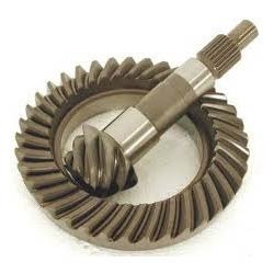
Ans : Bevel gears are mainly used to change the direction of the shafts rotation. Its main use is to transmit power between tow intersecting shafts. Their speciality lies in the fact that they transmit the power between two shafts which are at right angles to each other. Bevel gears are classified on the basis of their teeth which may be Straight, Spiral or Hypoid shape. The bevel gears can also be classified as internal, crown and external bevel gears depending upon the pitch angle.
{Image by : Cdang
This file is licensed under the Creative CommonsAttribution-Share Alike 3.0 Unported license}
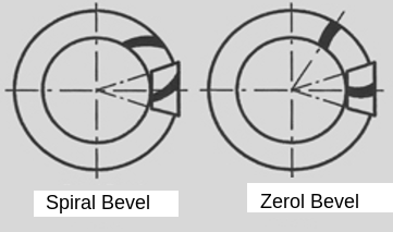
Spiral Bevel Gear :
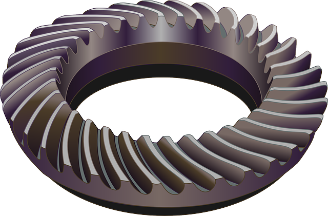
{Image : Creative commons licence, No attribution required}
Q.2. Compare Straight and Spiral Bevel gearing?
Ans :
| Point/Criterion | Straight Bevel Gear | Spiral Bevel Gear |
|---|---|---|
| Load Transfer | Sudden load transfer to next teeth | Gradual load transfer to next teeth |
| Noide | More noise | Less Noise due to smooth engagement. |
| Wear resistance | Less due to high contact stress | Less due to less contact stress |
| Applications | Slow speeed applications | high speed applications |
| Power transmitted | Used in lower power transmission. | Can transmit high power and at high speeds also. |
| Manufacturing cost | Easy to manufacture and hence the cost is less | Difficult to manufacture, needs sophisticated tools so cost is higher |
Q.3. What are different types of Bevel gears? Explain in brief each of them.
Ans : Bevel gears have following categories based on their elements and applications :
1. Miter gear 2. Crown gear 3. Straight bevel gears 4.Spiral bevel gear 5. Skew bevel gear 6. Hypoid bevel gear 7. Zerol bevel gears
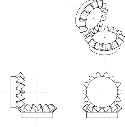
- Miter Gears : Miter gears are bevel gears which have same pitch, pressure angle, and number of teeth. Miter gears are two identical gears which are mounted on two shafts which are intersecting each other at 90 degrees. One such pair is shown below.
Both the gears are exactly same, so there is neither reducation or increment in speed but just change in the direction of motion from one shaft to another shaft.
- Crown Gear: A crown gear is a gear which has teeth that project at right angles to the face of the wheel.When pitch angle of one of the bevel gear is 900 , then that gear is called ‘Crown gear’. Such pair is used to connect two shafts which are intersecting each other at an angle more than 900. This gear is commonly used in atuombiles differential gear box, from where power is transmitted to wheel.
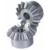
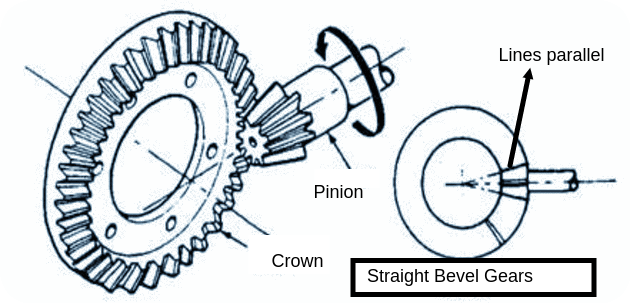
3. Straight bevel gears :In Straight bevel gears the teeth are straight and parallel to gernrators of cone. These are the simplest form of bevel gears.
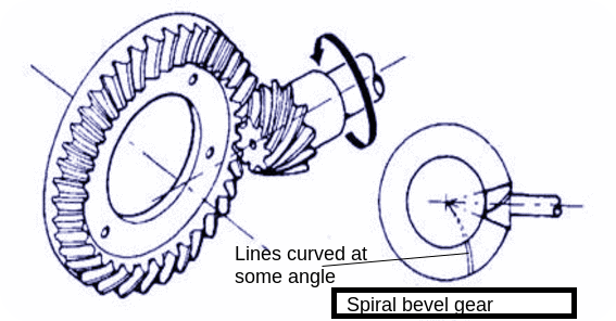
- Spiral Bevel gears : Spiral bevel gear have curved teeth set at an angle to the radial lines. This results in curved oblique teeth on which contact begins gradually and continues smoothly. This type of gear mesh allows more than one tooth to be in full contact {similar to helical gears in case of spur and helical gearing}, permitting greater loads than straight bevel gears. They are also smoother and quieter in operation, and can operate at higher loads and speeds.
- Skew bevel gear : A bevel gear in which the axis lie in different plane is called skew bevel gear. These are used for non parallel and non intersecting shafts. Skew bevel gears have straight teeth.
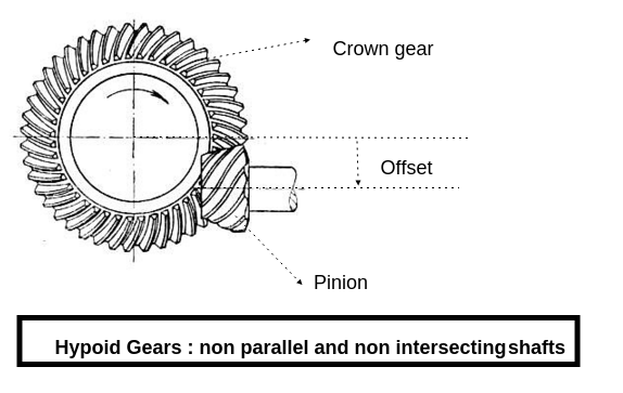
- Hypoid Gears : Hypoid gears are the spiral gears but the axis lie in different plane, means gears are mounted on non parallel and non-intersecting shafts. Hypoid gears have more friction than noramal spiral gears so special type of lubricants are required for them. Extreme pressure (EP) lubricants are used for hypoid gears. Further due to more friction they have less transmission efficiency. The main advantage of hypoid gears is that the pinion can be offset from the centre line of crown. This is particularly advantageous in automobile applications. Hypoid gears are suitable for the situation where smooth operation and higher reduction in compact space is required.
- Zerol bevel gear : Zerol bevel gears are spiral bevel gears , but the spiral angle of the teeth is zero. The Zerol bevel teeth will be slightly curved with one concave and one convex side.
Numerical Problems on BEVEL Gear Collected from Various universities
1) A BEVEL gear pair has 20° full depth involute BEVEL gears consist 24 and 72 teeth respectively. The module at outside diameter is 6 mm, while the face width is 50 mm. The gears are made of gray cast iron FG 220 (S ut = 220 N/mm 2 ). The teeth are generated and assume that the velocity factor accounts for the dynamic load. The pinion rotates at 300 rpm. The service factor is 1.5 and factor of safety is 1.75. (Assume b = A 0 /3, b = tau width, A 0 = pitch cone distance)
Calculate:
i) Beam strength of BEVEL gear
ii) The rated power .
iii) Surface hardness of gears.
2) A BEVEL gear pair has 20 teeth pinion and 60 teeth gear are in mesh with their axes intersecting at right angles and driven by an electric motor 5000 W power running at 1440 rpm. Take load concentration factor 1.2 and service factor 1.5. Both gears are made of plain carbon steel having ultimate tensile strength of 700 MPa and is hardened to 350 BHN. If module is 5 mm and the face width is 45 mm, deformation factor is 11400e , Calculate.
i) Factor of safety based on bending.
ii) Factor of safety based on pitting failure.
The gears are machined to give a combined tooth error 50 microns. Use Buckinghams equation given below
3) Two straight BEVEL gears intersecting at right angle have teeth pinion meshing with 32 teeth gear. The pinion shaft is connected to an electric motor developing 12000 W rated power at 1440 rpm. Starting torque of motor is 150% of rated torque. The pressure angle is 20°. Both gears are made up of case hardened steel (S ut = 750 N/mm 2 ). The teeth on gear are generated and finished by a grinding and lapping process to meet the requirement of class 3 grade. Factor of safety in preliminary stages of design is 1.5. C = 11400 N/mm 2 .
a) In initial stages of gear design assume that velocity factor account for dynamic load.calculate the module based on beam strength.
b)Calculate dynamic load using Buckinghams equation. Calculateout effective load. Maximum expected error between two meshing teeth (mm).

Module (m) mm Class 3
upto 4 0.0125
5 0.0125
6 0.0150
7 0.0170
8 0.0190
9 0.0205
10 0.02204) Two straight BEVEL gears with 20° pressure angle consists of 20 teeth pinion meshing with 30 teeth gear. The module is 4mm while the face width is 20mm. The pinion and gear material has a surface hardness of 400 BHN. The pinion rotates at 720rpm and receives 3 kW power from a motor. Taking service factor of 1.5 and Barth’s factor for dynamic loading Calculate the factor of safety in pitting.
5) The dimensions of a pair of BEVEL gears are given in Fig. below, The gear G delivers 5 kW power at 500 rpm to the output shaft. The bearing A and B are mounted on the output shaft in such a way that the bearing B can take radial as well as thrust load, while the bearing A can only take radial load. Calculate the reactions at the two bearings.

6) A pair of straight BEVEL gear with 20 full depth involute tooth profile consist of 24 and 48 teeth gear. The axes are right angle to each other. The module at large end of tooth is 6 mm while the face width is 50mm. The gear pair is made of gray cast iron FG 220. The teeths are generated, the surface hardness of gear pair is 250 BHN. The application factor and factor of safety are 1.5 and 2.0 resp. The pinion rotates at 300 rpm. Assume velocity factor accounts for dynamic load.
Calculate:
i) Beam strength
ii) Wear strength
iii) Maximum static load on gear
iv) Rated power that the gear can transmit7) A straight BEVEL pinion having 21 teeth to be made of alloy steel (S ut = 800 N/mm 2 ) is to mesh with a gear to be made of plain carbon steel (S ut = 720 N/mm 2 ). The axes of pinion and gear intersects at right angle. Gear pair is to transmit 20kW power from a spindle running at 500 rpm to a machine running at 300 rpm. The starting torque of the motor is 110% of the rated torque. The factor of safety required is 1.5. The tooth system is 20 o full depth involute. The gears are cut to meet the specifications grade 6. Hardness of gear pair is 350 BHN. The deformation factor C is 10900 e. N/mm. Design the gear pair. Use velocity factor for preliminary estimation and Buckinghams equation for precise estimation of dynamic load

8) A straight BEVEL gear pair is to be used to transmit 25 K W power from an electric motor rotating at 1500 rpm to a machine required to rotate exactly at 600 rpm. The axes of the pinion and gear intersect at right angles. The pinion and gear are to be made of plain carbon steel 55C8 ( S ut = 720 N/mm 2 ). The service factor and factor of safety are 1.25 and 1.75 respectively. The tooth system is 20° full depth involute. The gears are to be manufactured to meet the specifications of grade 6. The pinion and gear are to be case hardened to 420 BHN and 400 BHN respectively. Design the gear pair by using the velocity
factor, Kv = (6/6+V) and the Buckinghams equation for dynamic load. Take
- Log in to post comments