Bolted joints and welded joints
Bolted joints are mainly used as temporary fasteners, which can be connected or disconnected whenever required.
Mechanical engineering needs the components to be attached to each other temporarily or permanently for the functioning of the machine. Following are the three types of joints are used in mechanical engineering.
1) Welded joints,2) Riveted joints 3)Bolted joints
Welded joints are used where two parts of components are to be attached permanently. whereas bolted joints are used where two components are to be attached temporarily.
Questions and answers
Q.1. State the advantages and disadvantages of welded joints over riveted joints.
Following are the advantages of Welded joints
1) Riveted joints require additional cover plates, rivets and other parts which increase the weight of the system.
2) Welded assembly has less cost than riveted assembly.
3) Welded assembly can be easily altered or modified to meet the design changes.
4) The Production of welded assemblies is less as compared to riveted assembly.
5) Welded assemblies are tight and leak proof as compared to riveted joints
6) Rivet ting is not possible for odd shaped items where welding is feasible.
7) Welded Joints are stronger than riveted joints.
Following are the Limitations or disadvantages of the Welded joints over Rivetted joints
1) Welding results in thermal distortion of parts, thereby inducing the residual stresses in the parts. It needs additional heat treatment to get relieved of the induced stresses.
2) Welding to very thin sheets is not possible, which is feasible by rivetting only.
4) The strength and quality of the welded joint depends on the skill of the welder.
5) Welded joints need special inspection facility and skilled personnel.
6) Welded joints can not be dismantled easily for maintenance.
Q.2. State the advantages and disadvantages of Bolted joints(Threaded Joints).
Following are the advantages of Bolted joints
1) The parts are held by clamping force resulting from wedge action. So reliable joint is created.
2) Very easy to Assemble and dismantle without any special equipments.
3) Bolted joints result in compact assembly.
4) Bolted joints are very economical as compared to other joints
5) Bolts and nuts are standardized components, so easily and economically available everywhere, which makes maintenance easy.
6) No specially skilled labour is required for assembling or dismantling.
Following are the Limitations :
1) Bolted joints need the machine components to have holes, it may reduce the strength of that component or even may result in failure due to stress concentration.
2) Bolted joints may loosen when subjected to vibrations for longer time.
3) Assembling requires 'Man power', which increases the manufacturing cost of the total assembly.
4) Bolt or nut heads reduce the appearance value of the assembly, they need to be hidden with some other means.
5) In rotating components, protuding bolts can cause accidents.
6) Proper amount of tightening is required, orver or under tightening may result in damage to assembly or threads themselves.
Q.3. State the advantages and disadvantages of Rivetted Joints.
Following are the advantages of Rivetted joints,
1) Rivetted joints are more reliable than welded or bolted joints in situation where the assembly is subjected to vibration and imapct forces.
2) Rivetting can be done to all types of metal sheet, irrespective of their properties and thicknesses.
3) Rivetting does not alters the properties of the material.
4) Rivetting can be done and inspected by normal skilled workers.
5) Rivetted joints can be dismantled without much damage to the connecting components.
Following are the limitations of Rivetted joints
1) Material cost of riveted joints is more as compared to other joints.
2) Rivetted assemblies have more weight as compared to the other assemblies
3) Holes produced in the components for the rivetting may cause stress concentration, and more susecptible to fatigue failure.
4) Overall cost of rivetted joints is more than welded and bolted joints..
TYPES OF Problems in Bolted design
A) Design Of Cylinder Cover Bolts
B) Eccentrically Loaded Bolted Joints
1. Bolt axis parallel to direction of load.
2. Bolts in the plane of Load.
3. Bolt axis perpendicular to direction of load
A ) Design Of Cylinder cover bolts
The bolts are subjected to direct tensile stress due to pressure inside the cylinder. As shown in figure, the Force created on cover tries to push the cover up, this force is resisted by the bolts. Which results in Tensile stress in bolts.
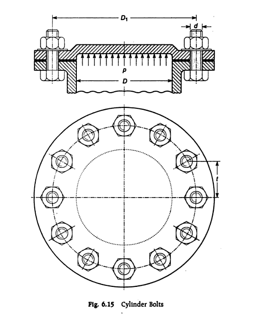
Step I)To find Force( Gas Load) Acting on cylinder cover
![]()
![]()
Step 2) To fine Size of the Bolt
![]()
![]()
![]()
Using this equation core diameter of bolts is determined if no of bolts are known ..
Outer diameter of bolt is found by using emperical relation
![]()
Numerical Problems On cylinder cover bolt design
Problem 1: A cylinder head of an engine is held by 12 bolts placed on a pitch circle. the effective diameter of cylinder is 350mm and Pmax is 0.75 N/mm2. Find the bolt size required if the allowable stress in the bolt material is 80 N/mm2.
Ans: M14
Prob.2. The effective diameter of cylinder bore is 400mm. The maximum pressure of gas acting on the cylinder cover is 1.12 N/mm2. Find the number of M24 (Major dia 24 mm) size studs required to fix the cover, If the stress is not to exceed 33.5 MPa. Assuming that bolts are not initially stressed..
Ans= n=16 Bolts
Prob 3: Cylinder head of steam engine is held in position using M20 Bolts. The effective diameter of the cylinder is 350mm and steam pressure is 0.75 N/mm2. Find the number of bolts required. take working stress for the bolt material 20 N/mm2.
Ans: n=18 bolts
Problem 4.A cylinder head is connected to cylinder flange by means of 16 bolts. The bor of the cylinder is 400mm. The maximum pressure inside cylinder is 1.25 N/mm2. The material of bolts is plain carbon steel 30c8 (syt=400 N/mm2) and factor of safety is 5.5. Find the size of bolts,neglecting the effect of initial tightening find the size of bolts.
Ans: M18 bolts
Problem 5. A cylinder head of engine is held in position by M20 Bolts. The bore of the cylinder is 300mm and pressure inside cylinder is is 1.5 N/MM2. Assuming the bolts are not stressed initially due to tightening effect. find the no of bolts required. if the tensile stress in bolts is not to exceed 50 N/mm2.
n=10 Bolts...
B) Eccentrically Loaded Bolted Joints
|
|
case 1) Bolt axis parallel to direction of load |
Case 2) Bolt axis in the plane of load |
Case 3 ) Bolt axis perpendicular to direction of load
|
|
Diagram |
|
|
|
|
Direct Load |
(Tensile) |
(Shear)
|
(Shear) |
|
Additional load due to Tilting |
(Tensile) l= Distance of bolts from tilting edge
|
(Shear) l= Distance of bolts from Centroid
|
(Tensile) l= Distance of bolts from tilting edge
|
|
Forces |
|
|
|
|
Equivalent Load |
Total equivalent load
(Tensile) |
Total Equivalent load
(Shear)
Only horizontal Line--angle 0.. Only vertical line--angle is 90. |
Total Equivalent Tensile load
Total Equivalent Shear Load
|
|
Bolt Size calculation |
|
|
|


Type 1: Bolt axis parallel to load
-
A bracket is attached to the ceiling with the help of two steel bolts, the bracket carries a load of 25000 Newtons and the allowablestress for bolt material in tension is 90 Mpa. The distance of first bolt from the leftmost edge is 100 mm, the distance between two bolts is 120 mm and the distance between leftmost edge and the line of application of load is 150 mm (Eccentricity) . Find the size of the bolt to take this load. Take the load direction is parallel to the bolt axis.
-
A bracket is attached to celling, as shown in figure below, It supports a load of 30000 N with the help of FOUR bolts, Determine the size of the bolts if the maximum allowable stress in the bolt material in tension is 60 MPA. The distances are , L1=80mm, L2=250mm and L=500mm
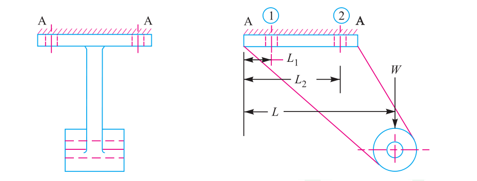
{Ans:dc=27.2 and d=33.75 The bolts should be of size M34.}
Type 2: Bolt axis Perpendicular to the Direction of load
1.A wall bracket, as shown in Fig. , is fixed to a wall by means of four bolts. Find the size of the bolts .The safe stress in tension for the bolt may be assumed as 70 MPa.
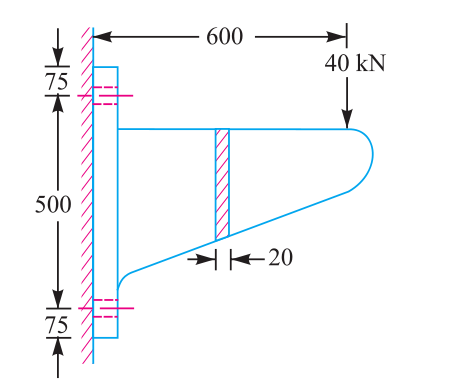
[Ans:dc=21.14, M28]
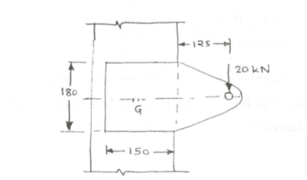
2.The brackets are fixed on steel columns as shown in Fig Vertical face of the bracket is secured to a column by four bolts, in two rows (two in each row) at distance of 50 mm from the lower edge of the bracket. Determine the size of the bolts if the permissible value of the tensile stress for the bolt material is 84 MPa.

{Ans: dc=10.65}
3. A bracket is fitted to wall by means of four bolts as shown in figure Find the size of the bolt if Allowable tensile stress = 50 MPa Allowable Shear stress = 30 Mpa

{By tensile strength M24, By shear strength M22, FInal size M24}
4. A wall bracket is attached to a wall by means of four identical bolts, two at A and two at B as shown in figure below.If allowable stress is 35 N/mm2, determine the size of the bolts on the basis of Maximum principal stress theory.

{dc=22.61,M30}
5..A bracket is fitted with the help of six bolts of identical size bolts to wall as shown in figure. Find the size of bolt if ft=42 MPa and Fs=35 MPa.

{dc=11.32,M16 and dc=9.42, M12..Final size M16}
Type 3: Bolt axis in the plane of load


l= Distance of bolts from Centroid of lamina connecting all bolts
Total Equivalent load
![]()
![]()
Location of centroid for the various configuration of bolts

DESIGN OF WELDED JOINTS
Key Points to Remember
- Welding can join objects of any shape and size but only of similar metallic materials, preferably steels.
- Welding causes permenant joint, once construsced can not be dismanteled.
- Welded joints are relatively strong,durable and reliable and can take complex loads.
- The quality of welded joint depends upon the manual skill of person performing welding
- Welded joints are less affected by vibrations, and they don't needs modification in origional structure like drilling holes, providing shoulders etc
- Welding causes metallurgical changes(Grain structure) in the vicinity of weld. It needs additional heat treatment to normalize this effect.
- Welding is not possible for very thin pates and structures.
- An eccentrically loaded weled joint is subjected to promary shear load and secondary shear load due to rotational effect of the load on the joint. HEnce overal process for designing a weld size is expeceted to same as that for the boltedjoint. But there is main dfference that in case of bolts there are fixed number of bolts whereas in case of welding joing there are small weld segments at different loactions.
- For analysis purpose we fing the centroid of the all welds and then take the distance of the extreme segment for determining secondary load/stress. For that purpose we also need to find the moment of inertia of welds.
- When the primary and secondary loads/stresses are known resultant stress is found with the formula
- The resultant shear stress obtained is used for finding the fillet size of weld.
- The strength of welded joint is determined considering the throat area which is equal to 0.707 times the thickness of the weld.
- For tensile failure as well as the shear failure throat area is 0.707 times thickness times the length of weld, is taken as the resisting area.
- In case of eccentric loading the Centroid of the whole weld area is found and it is assumed that the whole assembly tries to rotate about the centroid, the longest radius from centroid is determined using the geometric relations and then the secondary load/stress is determined.
Numerical Problems on Welded Joints
1) A steel bracket is welded to steel column as shown in figure below. Find the size of the weld if permissible shear stress in the weld is 80 MPa. All dimensions given are in milimeters
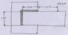
2) Figure shows a welded joint subjected to an eccentric load of 25000 N, if the permissible shear stress in the weld material is 55 MPa determine the size of the weld.Welding is only on one side.
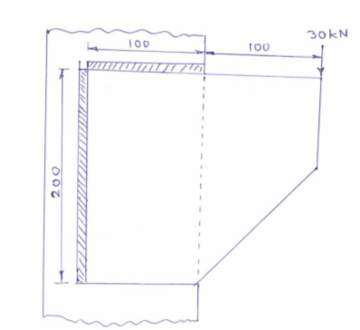
3) Figure shows an eccentrically loaded welded joint, if the allowable shear stress in the weld is 60 MPa and the load is static, determine the throat dimensions for the weld.
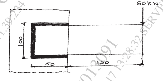
4) A welded bracket is shown in figure below, it carries a load of 60 KN st an eccentricity of 150 mm from the column. Determine the size of the weld if the allowable shear stress in the weld is limited to 100 MPa.
5) A plate 75 mm wide and 12.5 mm thick is joined with another plate by single transverse weld as well as two parallel fillet welds as shown in diagram below. The maximum tensile and shear streses are 75 MPa and 60 MPa respectively. Find the safe legth of each parallel fillet weld if the joint is subjected to static loading.
Links to other Topics in Machine design I
Machine Design I - Introduction to Design : Theory Q&A
Machine Design -I -Design of joints : Theory Q&A
Knuckle Joint : Design Procedure,Problems and Questions
Design of turnbuckle : Design steps, Problems and Question
Design of Levers : Hand Lever, Foot Lever, Bell crank lever
Design Of Bolted and Welded Joints
Design of Shafts: Theory and Numerical Problems
Couplings : Design Procedure and Numerical problems
Design Of SPRINGS : Questions and Numerical problems
Power Screw Design
Belt drives:Theory Q&A and Selection of Flat and V belts
- Log in to post comments