Cotter joint Design Procedure
Cotter Joint Introduction
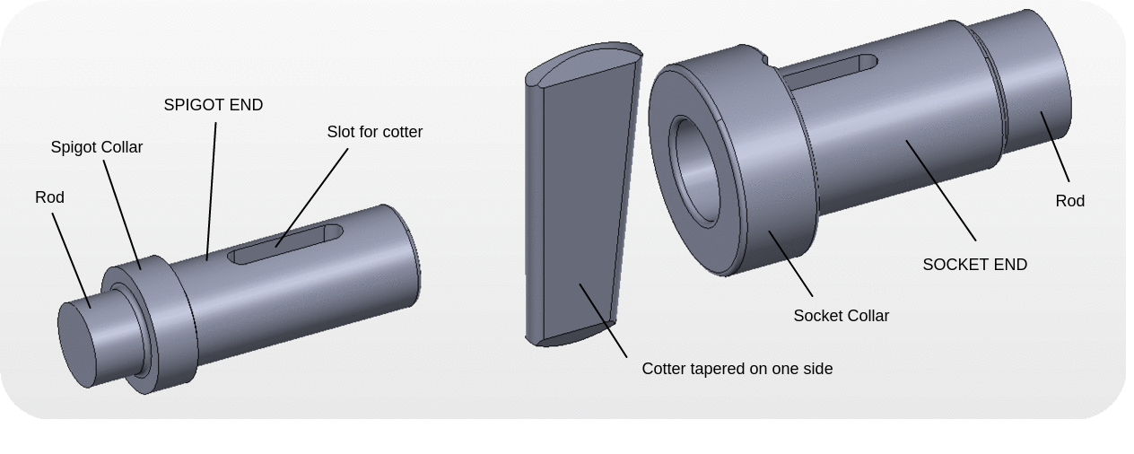
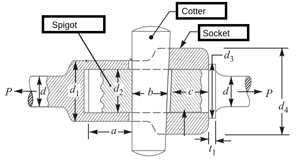
Cotter joint is demonstrated in figure below.Before going into detailed steps to design and find dimensions of cotter joint, it is necessary to understand clearly the various components, their functions and assembly of cotter joint. Here is the exploded view of cotter joint.
Let us see the animation of each component so as to get clear idea of its details and dimensions.
Spigot is the male part of the joint , it has a rectangular slot for passing the cotter through it. Spigot has a collar which rests against the socket end.
Socket is the female part of the joint, it also has a rectangular slot for passing the cotter through it. It has a circular hole in which spigot fits.
Cotter is a wedge shaped piece of metal which actually connects two parts which are non rotating. Cotter is fitted in the slot and remains in its position by wedge action.
Taper is provided to, i) With taper it is easy to remove the cotter and dismantle the joint ii) It ensures tightness of the joint in operation and prevents loosening of the parts.
Cotter is driven in or out using the hammer. Value of taper on cotter is 1 in 48 to 1 in 24 .
DESIGN PROCEDURE OF COTTER JOINT
Notations used in design are as follows,
P= Load on the joint or pull acting on rods, d= Diameter of the rod, d1= outer diameter of socket,d2= Diameter of spigot or inside diameter of socket, d3= Outside diameter of spigot collar,d4= Diameter of socket collar, t1= Thickness of spigot collar, a = Distance from the end of the slot to end of spigot, c= thickness of socket collar, b,t,l= width , thickness and length of cotter
Step 1 : Design of rod( ‘d’)
Tensile failure of rod

Since the area resisting is circular using the basic equation of design
Load = Stress * Area
...From this equation diameter d of the rod is determined.
Step 2 : Design of Spigot { ‘d2’,’d3’,t1’,’a’}
Tensile failure of Spigot
The spigot end may fail under tension into two parts as shown in figure below, Since the plane of failure is perpendicular to the direction of force it is tensile failure,
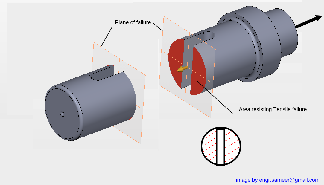

the area resisting the failure is shown by red in the diagram, since it is circular minus a rectangle the equation will be,
![]() ………….From this equation the diameter of spigot end d2 can be found. If you observe clearly it will form a quadradic equation .
………….From this equation the diameter of spigot end d2 can be found. If you observe clearly it will form a quadradic equation .
Emperical Relations
{Other three dimensions of Spigot are decided on the basis of emperical relations and then checked whether the stress induced is withing safe limits or not}
Crushing failure of Spigot ( Check crushing stress induced)
……...Find
Using this equation and check if it is within safe limits or not .
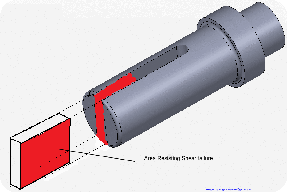
Shear failure of Spigot ( Check Shear stress induced)
……...Find
Using this equation and check if it is within safe limits or not .
Diagram showing the Shear failure of Spigot end
Step 3 : Design of Socket { ‘d1’,’d4’,’c’}
Following dimensions of socket are to be found and stresses induces must be checked for safe limit.
Tensile failure of Socket
The socket may also fail under tension into two parts as shown in figure below, since the plane of failure is perpendicualr to direction of force it is the tensile failure.
Area resisting is a hollow square minus a rectangular strip having length (d1-d2) and thickness t, so the strength equation becomes,
![]() ………...From this equation diameter d1 can be determined, again there is quadradic equation formation. Refer to numerical problems section to view the detailed solution.
………...From this equation diameter d1 can be determined, again there is quadradic equation formation. Refer to numerical problems section to view the detailed solution.
Emperical Relations
{Other three dimensions of Socket are decided on the basis of emperical relations and then checked whether the stress induced is withing safe limits or not}
Crushing failure of Socket( Check crushing stress induced)
……...Find
Using this equation and check if it is within safe limits or not .
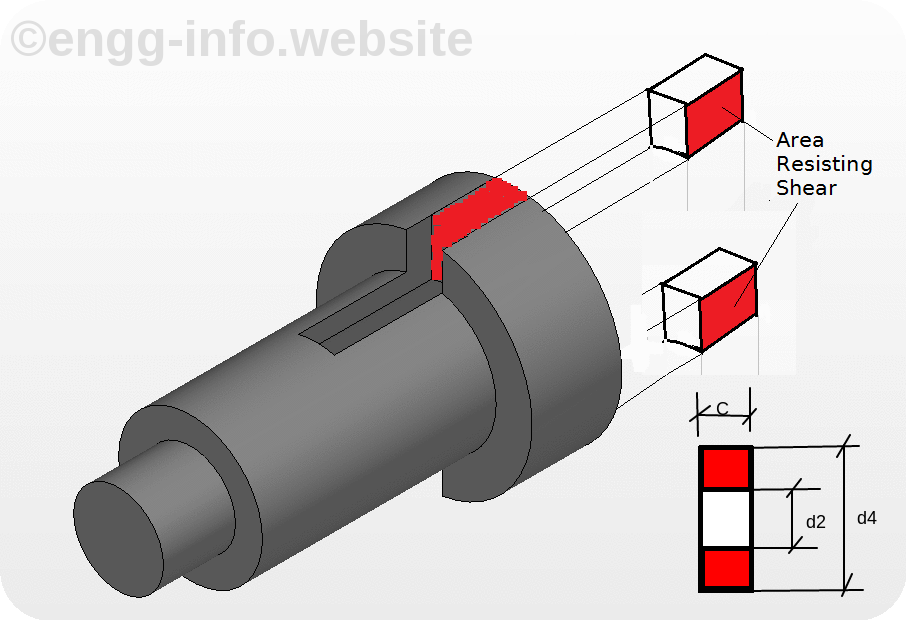
Shear failure of Socket ( Check Shear stress induced)
……...Find
Using this equation and check if it is within safe limits or not .
Shear Failure of socket end is shown below
Step 4 : Design of Cotter { ‘t’, ‘b’ and ‘l’ of cotter}
Empirical relation
The cotter thickness is determined using an empirical relation, and is proportional to the diameter of rod,
Calculate the width of b of the cotter by sharing and bending consideration
Double shear of Cotter
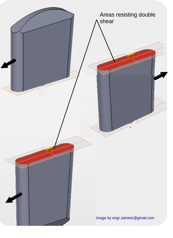
{Note that 2 is because of double shear failure}
Bending failure of cotter
{This formula is based on the bending stress induced in the cotter, the derivation of this formula is described in the theory section of this chapter}
Design procedure of cotter joint in tabular form {Grouped for easy to remember steps}
Step |
Component |
Criterion |
Design equation |
To find |
|---|---|---|---|---|
| 1 | Rod | Tensile Failure | d= ‘ ‘ | |
| 2 | Spigot |
Tensile Failure Emperical relation
Crushing Failure
Shear Failure |
|
d2 =’ ‘ d3= ‘ ‘ t1 = ‘ ‘ a = ‘ ‘
|
| 3 | Socket |
Tensile Failure Emperical relations
Crushing Failure Shear Failure
|
|
d1 = ‘ ‘ d4 =’ ‘ c = ‘ ‘ |
| 4 | Cotter |
Emperical Relation Double shear Bending failure |
|
t = ‘ ‘ b= ‘ ‘ b= ‘ ‘ {Choose higher b of both above} |
B) Numerical Problems
1) Design and draw a detailed sketch of cotter joint which is required to withstand a load of 30 kN in tension and compression. The material used for the cotter joint has following allowable stress values

Allowable stress in tension =50 MPa,

Shear Stress =35 Mpa

Crushing stress= 90 Mpa
2) Design and draw cotter joint required to withstand a load of 45 kN, The cotter joint is made up of material having following allowable stresses

Allowable stress in tension =55 MPa

Allowable shear stress = 40 MPa

Allowable Crushing stress = 70 MPa
3) It is required to design a cotter joint which is used to connect two steel rods having same diameter. The maximum axial load on the joint is 50 kN. The material used for joint is 30C8 ,ultimate tensile stress for the material is 400 MPa. Using factor of safety 6. Design all dimensions of the joint. Take ultimate shear stress half that of ultimate tensile stress and Ultimate Crushing stress double that of ultimate tensile stress. Draw the neat dimensioned sketch of the joint designed showing all important dimensions.
4) A cotter joint carries a load of 150 kN, is made up material 45C8. The ultimate tensile stress is 500 MPa. Using factor of safety of 4 design the joint.Take ultimate shear stress half that of ultimate tensile stress and Ultimate Crushing stress double that of ultimate tensile stress. Draw the neat dimensioned sketch of the joint designed showing all important dimensions.
5) Design and draw cotter joint required to withstand a load of 200 kN, The cotter joint is made up of material having following allowable stresses

Allowable stress in tension =65 MPa

Allowable shear stress = 45 MPa

Allowable Crushing stress = 125 MPa
6) Design and draw cotter joint required to withstand a load of 120 kN, The cotter joint is made up of material having following allowable stresses

Allowable stress in tension =95 MPa

Allowable shear stress = 65 MPa

Allowable Crushing stress = 186 MPa
C) THEORY QUESTION AND ANSWERS ON COTTER JOINT
Q.1) State applications of Cotter Joint .
Ans : Following are the some of the applications of cotter joint. Mainly it is used to connect two rods which are not rotationg and which carry tensile as well as compressive load.
1) It is used in bicycle for connecting pedal to sprocket wheel.
2) It is also used for connecting piston rod and the cross-head of steam engine.
3) It is used for connecting piston rod with the tail or pump rod
4) It is used in Foundation bolts.
Q.2) What is a Cotter ? Why taper is provided on cotter? How much taper is provided?
Ans : Cotter is a flat wedge shaped part which is used to connect two rods which transmit the force/motion but without rotation. Cotter is fitted in the tapered slot and remains in its position by wedge action.
Because of taper,
i) It is easy to remove the cotter & dismantle the joint
ii) It ensures tightness of the joint in operation & prevents loosening of the parts.
Value of taper on cotter is 1 in 48 to 1 in 24.
Q.3) Why in a cotter joint the cotter is kept weakest?
Ans : In the whole assembly the cotter is the part with least material and easy to replace, hence for this economical and practical reason cotter is kept weakest, so that it can be replaced on failure. It generally fails in shearing or bending.
Q.4) State the advantages of cotter joint.
Ans : 1) Easy assembling and dismantling: It is assembled by hammering in the cotter and dismanteled by removing cotter.
2) Strong grip froce: Due to wedge action there is very strong tightening force which prevents loosening mf parts.
3) Simple to design and manufacture.
D) OBJECTIVE QUESTION AND ANSWERS ON COTTER JOINT
1) Assertion (A): A cotter joint is used to rigidly connect two coaxial rods carrying tensile load.
Reason (R): Taper in the cotter is provided to facilitate its removal when it fails due to shear.
(a) Both A and R are true and R is the correct explanation of A
(b) Both A and R are true but R is NOT the correct explanation of A
(c) A is true but R is false
(d) A is false but R is true
Answer : (b) Both A and R are true but R is NOT the correct explanation of A
The purpose of providing taper is to have wedging action and also ease of assembling and dismantling, the taper has nothing to do with tensile load carrying capacity of joint. Hence option (b) is correct answer.
2) The spigot of a cotter joint has a diameter D and carries a slot for cotter. The permissible crushing stress is x times the permissible tensile stress for the material of spigot where x > 1. The joint carries an axial load P. Which
one of the following equations will give the diameter of the spigot?

Answer : (b)
3) A cotter joint is used when no relative motion is permitted between the rods joined by the cotter. It is capable of transmitting
- (a) Twisting moment
- (b) The bending moment
- (c) an axial tensile as well as compressive load
- (d) only compressive axial load
Answer : (c)
4) 1. Cotter joint is used when the members are subjected to ...
a) Axial tensile forces only
b) Axial compressive forces only
c) Axial tensile or compressive forces
d) None of the mentioned
Answer : (c)
5) The piston rod of a steam engine is usually connected to the cross head by means of
- Bolted joint
- Knuckle joint
- Turn buckle
- Cotter Joint
Answer : (4)
Links to other Topics in Machine design I
Machine Design I - Introduction to Design : Theory Q&A
Machine Design -I -Design of joints : Theory Q&A
Knuckle Joint : Design Procedure,Problems and Questions
Design of turnbuckle : Design steps, Problems and Question
Design of Levers : Hand Lever, Foot Lever, Bell crank lever
Design Of Bolted and Welded Joints
Design of Shafts: Theory and Numerical Problems
Couplings : Design Procedure and Numerical problems
Design Of SPRINGS : Questions and Numerical problems
Power Screw Design
Belt drives:Theory Q&A and Selection of Flat and V belts
- Log in to post comments