1. Description of the Ideal Vapour Compression Cycle on the P-H Diagram
The Pressure-Enthalpy (P-H) diagram is the most practical representation for the VCS, as the system's performance metrics (work and heat) are directly proportional to changes in enthalpy (h).
The diagram features a saturation dome, with the saturated liquid line on the left and the saturated vapor line on the right. The cycle is composed of four distinct points connected by four processes:
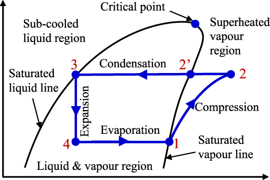
State Points:
- Point 1 (Compressor Inlet): Saturated vapor, located exactly on the saturated vapor line at the low evaporating pressure (PL). It has enthalpy h1 and entropy s1.
- Point 2 (Compressor Outlet / Condenser Inlet): Superheated vapor, located in the region outside the dome (above and to the right of the dome). It has high pressure (PH) and high enthalpy (h2).
- Point 3 (Condenser Outlet / Expansion Valve Inlet): Saturated liquid, located exactly on the saturated liquid line at the high condensing pressure (PH). It has enthalpy h3.
- Point 4 (Expansion Valve Outlet / Evaporator Inlet): Wet vapor (a mixture of liquid and vapor) located under the saturation dome at the low evaporating pressure (PL). It has enthalpy h4.
Cycle Processes:
- Process 1-2 (Isentropic Compression):
- Representation: A line sloping upwards and to the right, starting from the saturated vapor line (PL) and extending into the superheated region (PH).
- Thermodynamics: This is an isentropic (constant entropy, s1=s2) process where the compressor performs work (Win). Pressure and temperature increase significantly.
- Key Value: Work Input is determined by the enthalpy change: Win=h2−h1.
- Process 2-3 (Isobaric Heat Rejection / Condensation):
- Representation: A line moving horizontally from the superheated region (Point 2) across the diagram until it hits the saturated liquid line (Point 3) at the constant high pressure PH.
- Thermodynamics: Heat is rejected to the environment or cooling medium (QH). The refrigerant desuperheats, condenses at a constant temperature, and leaves as saturated liquid.
- Key Value: Heat Rejected is determined by the enthalpy change: QH=h2−h3.
- Process 3-4 (Isenthalpic Throttling / Expansion):
- Representation: A vertical straight line moving downwards from the high-pressure saturated liquid line (PH) to the low-pressure wet vapor line (PL).
- Thermodynamics: This is an irreversible, isenthalpic process (h3=h4). The pressure drops suddenly, causing the liquid to flash into wet vapor.
- Key Value: Enthalpy is constant: h3=h4.
- Process 4-1 (Isobaric Heat Absorption / Evaporation):
- Representation: A horizontal line moving to the right, staying under the saturation dome at the constant low pressure PL, starting from Point 4 and ending at the saturated vapor line (Point 1).
- Thermodynamics: Heat is absorbed from the refrigerated space (QL). The wet vapor evaporates at a constant temperature, leaving as saturated vapor.
- Key Value: Refrigerating Effect is determined by the enthalpy change: QL=h1−h4.
2. Description of the Ideal Vapour Compression Cycle on the T-S Diagram
The Temperature-Entropy (T-S) diagram is useful for visualizing the theoretical efficiency and the irreversibility associated with the throttling process. The diagram also features the saturation dome with lines representing the liquid and vapor phases. The horizontal axis is Entropy (S), and the vertical axis is Temperature (T).
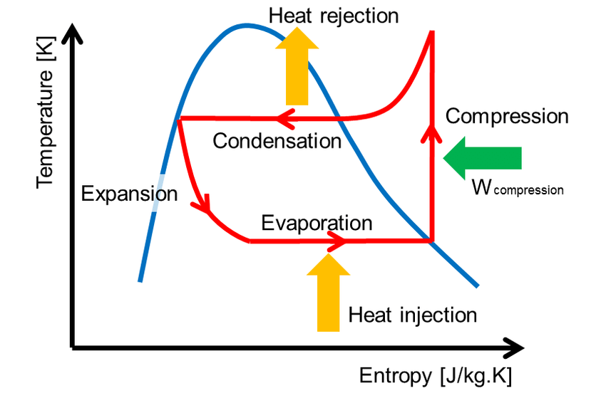
Cycle Processes:
- Process 1-2 (Isentropic Compression):
- Representation: A vertical straight line moving upwards, starting from the saturated vapor line (Point 1) and extending into the superheated region (Point 2).
- Thermodynamics: This ideal compression is isentropic (s1=s2). The temperature rises from the evaporating temperature (TL) to the superheated temperature (T2).
- Process 2-3 (Isobaric Heat Rejection / Condensation):
- Representation: A curved line sloping down and left in the superheated region (desuperheating), followed by a horizontal line moving left under the dome at the constant high condensing temperature (TH), ending at the saturated liquid line (Point 3).
- Thermodynamics: Heat (QH) is rejected. The refrigerant transitions from superheated vapor to saturated liquid.
- Process 3-4 (Isenthalpic Throttling / Expansion):
- Representation: A curved line sloping downwards and to the right, starting from the saturated liquid line (Point 3) and ending in the wet vapor region (Point 4) at the low temperature TL.
- Thermodynamics: This is an irreversible process. Although enthalpy is constant, entropy increases significantly (s4>s3). The temperature drops from TH to TL.
- Process 4-1 (Isobaric Heat Absorption / Evaporation):
- Representation: A horizontal straight line moving to the right under the saturation dome at the constant low evaporating temperature (TL), starting from Point 4 and ending at the saturated vapor line (Point 1).
- Thermodynamics: Heat (QL) is absorbed. The area under this horizontal line represents the refrigerating effect.
- Log in to post comments