A) Knuckle Joint Design Procedure
Before going into detailed steps to design the dimensions of the Knuckle joint, it is essential to get oriented with all its components and their functions. Here is the diagram showing the exploded view of Knuckle Joint.
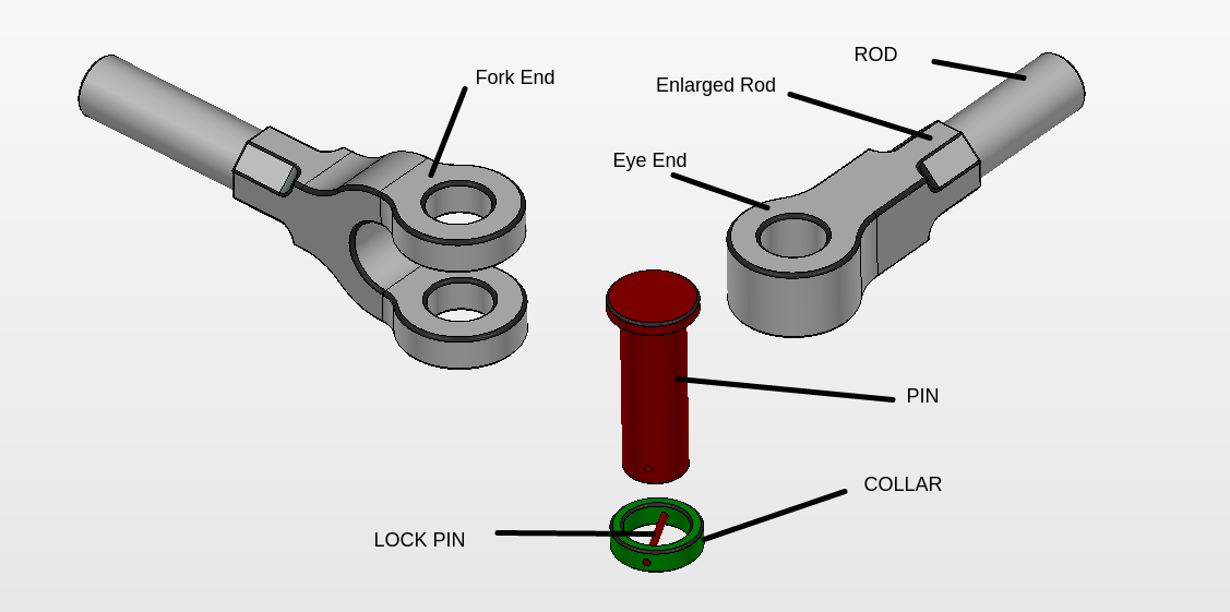
As seen in the assembly the Knuckle joint has main four parts
- Rods {Which are to be connected by joint }
- Single eye {Modified rod for assembly}
- Double eye or Forked end {Modified rod for assembly}
- Pin {Connects the two rods}
- Collar {to keep the pin in position}
- Split pin or taper pin {Not in diagram} {to prevent sliding away of pin}
Assembly Drawing and Notations used in Knuckle Joint
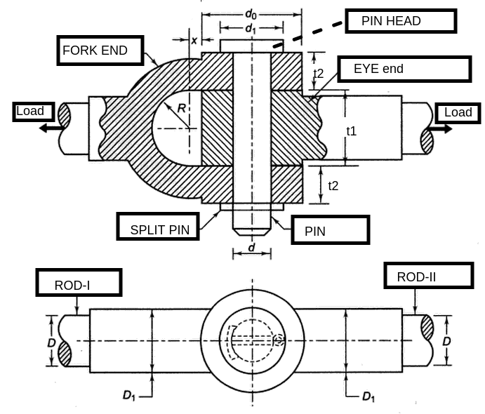
Notations used in design :
P = Tension in rod ( Load on the joint)
D = Diameter of rod
D1= Enlarged diameter of rod
d = Diameter of pin
d1 = Diameter of pin head
d0 = Outer diameter of eye or fork
t1 = thickness of eye end
t2= thickness of forked end (double eye)
x= distance of the Centre of fork radius R from the eye
STEPS TO DESIGN KNUCKLE JOINT
Step 1 : Design of Rods (D,D1)
Tensile failure of rod
Using basic strength equation
Load = Stress * Area
From This equation Diameter ‘D’ of rod can be found
Empirical relations
Using Empirical relations the enlarged diameter of rod D1 is determined
Step 2 : Decide the thickness of eye end and forked end (t1,t2)
Empirical relations
Both these dimensions are decided on the basis of empirical relations,
t1= 1.25 D and t2= 0.75 D
Step 3 : Decide the dimensions of pin (d,d1)
Double shear Failure
The pin may get sheared off into three pieces as shown below, since the pin breaks at two places it is called double shear. Both areas are taken as resisting areas.
Using basic strength equation
Load = Stress * Area
Note that 2 is because of double shear ...From This equation Diameter ‘d’ of pin can be found. But since the pin is also subjected to bending one more diameter of pin on the basis of bending is determined and the bigger of both is taken as the final size of pin
Bending failure of pin
The diameter on the basis of bending is determined using the following formula,
…..Calculate d from this formula
{ Discussion on how this formula is obtained is in the theory question and answer section of knuckle joint }
Empirical relation for pin head diameter
Since pin head is not subjected to any stress, its diameter is simply decided on the basis of proportionality, (it is taken 50% more than that of pin diameter )
d1=1.5 d
Step 4 : Check Stresses in Eye end
Empirical relation for outside diameter of eye and fork
d0=2d
Tensile failure of eye end
The single eye may fail in tension as shown below { please note that when the plane of failure is perpendicular to the direction of force then the failure is either tensile or compressive}
Using the basic equation for stress
………….Using this equation find the value of
and check if it is less than allowable value for design to be safe.
{Note that area resisting the tension is rectangular one and not circular so its area is length time height total length is (d0-d) and height is t1.
Shear failure of eye end
The single eye may fail in shear as shown below { please note that when the plane of failure is parallel to the direction of force then the failure is Shear failure}
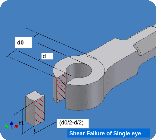
Using the basic equation for stress
simplifying this equation we get
………….Using this equation find the value of
and check if it is less than allowable value for design to be safe.
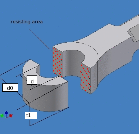
Crushing Failure of eye end
The single eye is also subjected to Crushing between pin and inner face of single eye. In case of crushing failure since the area is curved we take the projected (area which would be visible in drawing) of the cylindrical area. As we know that a cylinder appears as a rectangle in projection, hence the area will be diameter times the height of cylinder. This area is illustrated below,
Using the basic equation for stress
………….Using this equation find the value of
and check if it is less than allowable value for design to be safe.
Step 5 : Check Stresses fork end
Fork end is also subjected to same failures as that of eye end, the only difference is that it has two eyes. So we get the same equations except multiplied by 2.
The equations for tensile, shear and crushing failures are given below
Tensile failure of fork end
{see the changes highlighted in red from the equation of single eye} Get the value of induced tensile stress from this equation and confirm that it is below allowable tensile stress.
Shear failure of fork end
{see the changes highlighted in red from the equation of single eye} Get the value of induced shear stress from this equation and confirm that it is below allowable shear stress.
Crushing failure of fork end
{see the changes highlighted in red from the equation of single eye} Get the value of induced crushing stress from this equation and confirm that it is below allowable crushing stress.
Summary of Design Procedure in Tabular form
{ Student preparing for exam find the tabular form very handy and easy to remember the formulae }
Step |
Failure |
Equation |
To find |
|
Step 1 : Design of Rods (D,D1) |
Tensile
Empirical |
|
D= D1= |
|
Step 2 : Decide the thickness of eye end and forked end (t1,t2) |
Empirical relations |
t1= 1.25 D t2= 0.75 D |
t1 = t2 = |
|
Step 3 : Decide the dimensions of pin (d,d1) |
Double shear Bending failure
Empirical |
d1=1.5 d |
d =
d= {Choose higher value of both} |
|
Step 4 : Check Stresses in Eye end |
Empirical Tensile Shear Crushing |
d0=2d |
d0= check check check |
Step 5 : Check Stresses fork end |
Tensile Shear Crushing |
|
check check check |
NUMERICAL PROBLEMS
1) It is required to design a Knuckle joint to connect two circular rods which are subjected to an axial tensile load of 50 kN. the material used for joints is 50c8, having yield point stress 400 N/mm2. taking factor of safety as 5, find the all dimensions of Knuckle joint.
2) A Knuckle joint carries an axial load of 100 kN. it connects two circular rods which are made up of material 40c8, having yield strength 360 N/mm2. using factor of safety 4 design and draw the Knuckle joint. Show all important dimensions in the final drawing.
3) Design a Knuckle joint to transmit a load of 50 kN, assume permissible stresses as 40 N/mm2 in 10 size 40 N/mm2 in shear and 80 N/mm2 in compression.Also draw neat dimensioned sketch of Knuckle joint showing all important dimensions designed.
4) designer Knuckle joint subjected to a pull of 30000N.  assume permissible stresses as below,

 allowable tensile stress 80 N/mm2

allowable shear stress  60 N/mm2

 allowable crushing stress  120 N/mm2
5) A knuckle joint is required to transmit a load of 150 kN. the rod end, fork end  and pin are made up of same material.  The design stresses may be taken as

 allowable tensile stress 75 N/mm2

 allowable shear stress 60 N/mm2

 allowable crushing stress 150 N/mm2
6) It is required to design a Knuckle joint for a tie rod of circular cross section, the joint is subjected to maximum Pull of 70 kN. the ultimate strength of the material of the rod against tearings is 420 Mpa . the ultimate tensile and shearing strength of pin material or 510 Mpa and 400 Mpa respectively. Design the single eye, double eye and pin. Take factor of safety is equal to 6
7)Design a knuckle joint required to connect two  steel bars subjected to a tensile load of 25 kN. The allowable stresses are
75 MPa in tension,
60 MPa in shear and
100 MPa in crushing. Also draw the neat dimensioned sketch of the joint showing all important obtained dimensions.
8) Two MS rods are to be connected by a knuckle joint, load it has to transmit  is  120 kN. Design the joint assuming that the working stresses for both the pin and rod materials to be,

85 MPa in tension,

70 MPa in shear and

140MPa in crushing.
C) Theory Questions and answers on Knuckle joint
Theory questions are available here - Theory Questions Link
D) Objective type Questions and answers on Knuckle joint
Links to other Topics in Machine design I
Machine Design I - Introduction to Design : Theory Q&A
Machine Design -I -Design of joints : Theory Q&A
Knuckle Joint : Design Procedure,Problems and Questions
Design of turnbuckle : Design steps, Problems and Question
Design of Levers : Hand Lever, Foot Lever, Bell crank lever
Design Of Bolted and Welded Joints
Design of Shafts: Theory and Numerical Problems
Couplings : Design Procedure and Numerical problems
Design Of SPRINGS : Questions and Numerical problems
Power Screw Design
Belt drives:Theory Q&A and Selection of Flat and V belts
- Log in to post comments