Lever design basics
Lever design Key points to remember regarding design of levers :
Lever design is about finding the dimensions of the levers so that it could perform its function satisfactorily. A lever is force multiplier, depending upon the location of the load and effort from the fulcrum point. Levers are classified on the basis of location of load, effort and fulcrum point. Levers are found in numerous machines and devices serving different purposes, mainly force transmission with multiplications. Levers make our day to day life easier,they make ease in lifting, ease in cutting, ease in holding, ease in opening tight things. Hammer claws, wheel barrows, pickup tonges, Scicors, bottle openers etc.are the examples of day to day use of levers. A lever is meant to make the work easy, so it actually reduces the effort required to do a work. The effort is always less than the load, otherwise the lever or machine will be useless. In mechanical engineering numerous applications have levers used in them. Mainly to transmit the force. Lever design is important part of machine design. Hence a mechanical engineering must learn lever design. Lever design is based on the basic equations of Bending and Torsion. Lever design takes into consideration the bending failure and torsional failures of shaft.
Q.1. What is a mechanical Lever? What are its types?
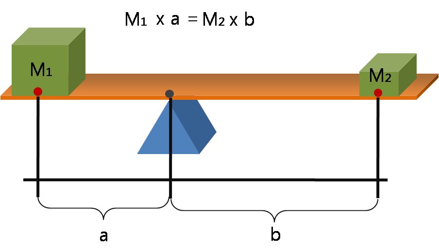
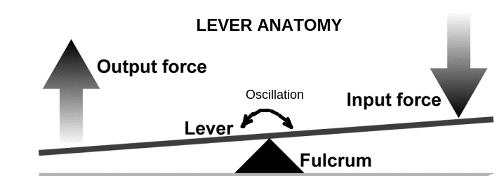
Ans : A lever is defined as a mechanical device in the form of a rigid link which is pivoted about a fulcrum to transfer or multiply the force.A lever is used for transmitting a force at one location to a different location alongwith change in direction or even change in magnitude of the force. When the magnitude of the force is increases than that of input force, it is called the mechanical advantage of lever or simply LEVERAGE. A lever includes a rigid structure that oscillates around a fixed point called the fulcrum.
LEVERAGE example.{Source Wikipedia} : A 5 kg weight balances the 100 kg weight because the distance of 5 kg weight from the fulcrum is more and that of 100 kg is less, the moment of both forces from the fulcrum is same.

Anatomy of the lever 1) Fulcrum : Point around which the lever Oscillates/rotates.
2) Input Force : Force exerted on the lever
3)Output Force : Force exerted by the lever
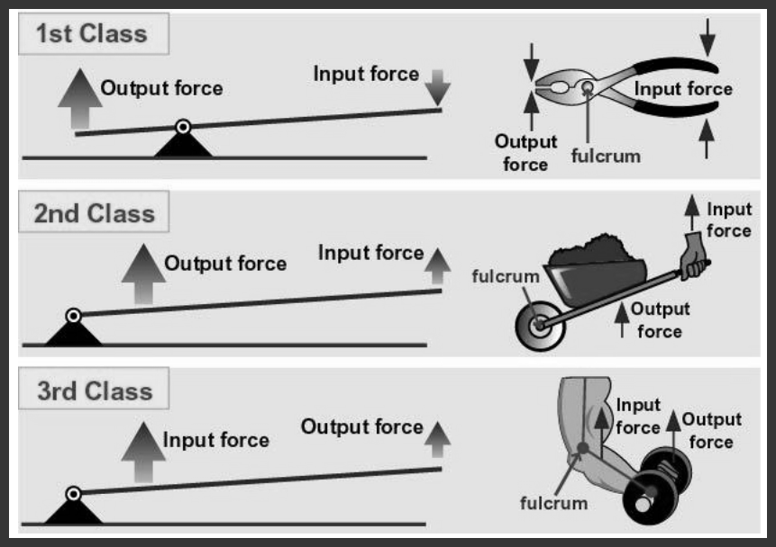
Three Classes of Levers
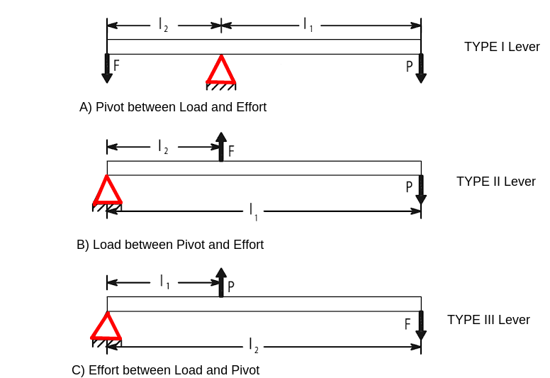
There are three types or classes of levers which are based on the relative positions of the effort point, the load point and the fulcrum.
They are as follows:
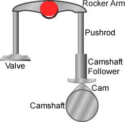
First Class - In this type the fulcrum between Input and output.This type of lever is used in applications like bell crank levers in railway signal mechanism,the rocker arm for the overhead valves of internal combustion engine, and levers of hand pump .
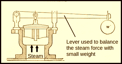
Second Class – In this type output between fulcrum and input.This type of lever is used in spring loaded safety valve mounted on the boilers.
Third Class – In this type input between fulcrum and output. This type of lever is not recommended in engineering applications. A picking fork is best example of this type of lever.
Q.2. What are the stresses induced in the lever? How it is designed
Ans : A lever acts like a cantilever from the pivot. A force acting at any end of the lever tries to bend the lever and hence acts as abending force. Hence the prime effect of a force at the end of the lever is to create a BENDING STRESS on the lever cross section. It is known to us that any bending stress is always of either tensile or compressive nature. The lever is generally made up of a convenient cross section like rectangle, square, I section etc. Due care is taken to see that the section modlus of the cross section is larger.
A lever is designed using the bending equation,
Where M= Bending moment { Either ) Whichever is larger
I= Moment of inertia
Allowable bending stress
y = Distance of extreme fibre from neutral axis .( for most sections it is half the depth of section)
Q.3. What is rocket arm? Where it is used?
Ans : In four stroke IC engines, there are inlet and outlet valves for the purpose of sucking the air( or charge) in the cylinder and pushing the exhaust gases after the exhaust stroke into the surrounding. This vale is opened and closed by a rocker arm, through cam action and push rod as shown below.
Q.4. Enlist Various applications of lever in Mechanical engineering? Illustrate with diagrams wherever necessary.
Ans : Levers are used for variety of applications in mechanical engineering for the purpose of transmitting or magnifying the force.
Following are the examples which show their use in mechanical engineering.
1) Application of lever in Boilers
2) Applicaiton of lever in I C Engines.
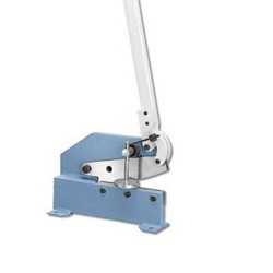
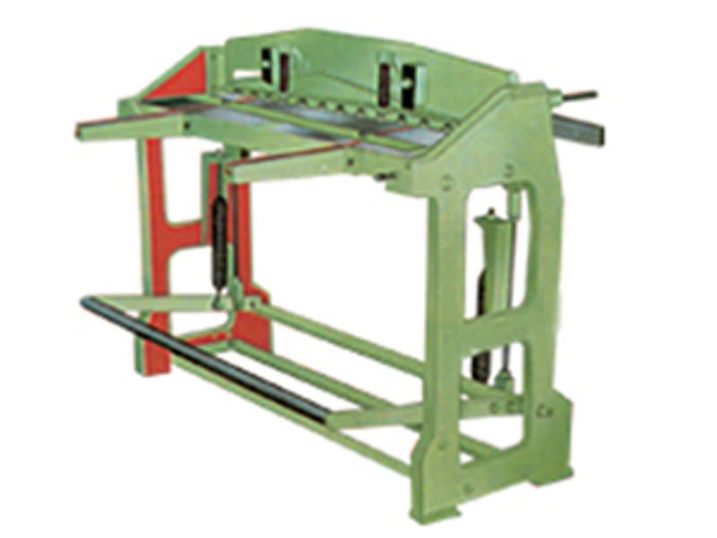
3) Application of lever (Foot lever and hand lever)
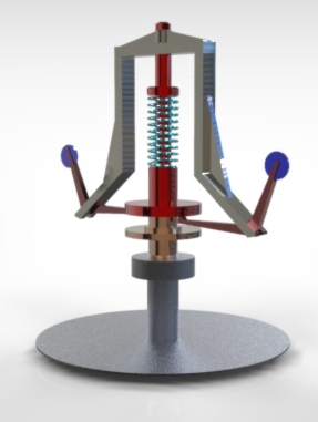
4) In governors bell crank levers are used.
5) Levers in Robotics : Hundreds of levers are used in robot and robotic machines
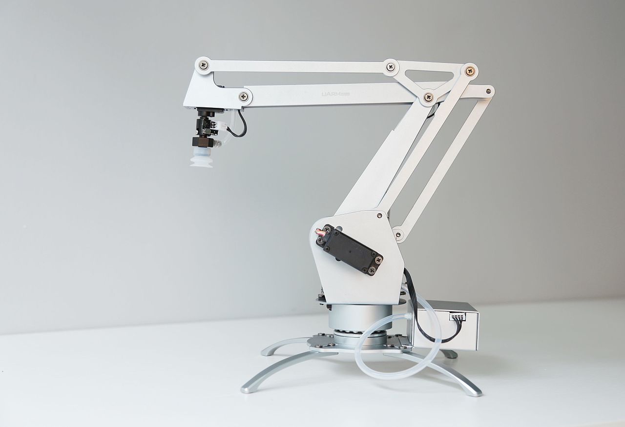
(IMAGE BY : Siaopan ,
- CC BY-SA 4.0 Source : Wikipedia)
Lever design Principles
Levers are found everywhere in the machines and automobiles, out of them the hand lever and foot levers are those which are manually operated for actuation of some action like shifting gear or applying brake etc. The basic principle behind the design of hand and foot lever is that it shoulf withstand the force and should not fail in bending. To avoid the bending or bending failure of the hand or foot lever it is necessary that the section of the lever should have the sufficient moment of inertia to resist the bending. For this purpose the hand and foot levers are made of rectangular or I sections with vertical side bigger than the horizontal side. The dimensions of crosssection are determined on the basis of flexural formula, which is the relation between bending moment, moment of inertia and the bending stress induced in the section. The induced bending stress should be less than the allowable bending stress for the material. In addition to the lever cross section there is a boss which is also to be designed based on the torsional shear stress induced in it, also the shaft which is rotated by lever is also designed first on the basis of the torsional shear stress induced.
Lever design Steps
Lever design Force Analysis
A lever is a bar which can rotate about a fixed axis called fulcrum axis, which is actually pin on which the lever is mounted. The basic purpose of a lever is to lift a load or apply a force, through an effort aplied at another point. The shape of the lever is conveniently choosen with respect to the requirement and applications, they include rectangular, eliptical or I section. The principle of operation of lever is based on the law of moments about a point.
Taking moment about the fulcrum we can find the effort and load acting on the lever, this give us F(Load) or P(Effort),

The resultant force acting at the fulcrum is given by,

If the lever is bell crank lever tha angle theta is 900 and as cosine of 900 is zero the formula reduces to first two terms only.
Design of Fulcrum Pin :
The fulcrum pin is subjected to the resultant reaction R, as calculated above. The pin is designed on the basis of allowable bearing pressure and shear stress induced.
Generally the length of pin is assumed to be 1.25 times the diameter of pin for ease of calcualtion.
 ......................This equation is used to determine the diamter and length of the pin.
Then the actual shear stress induced in the pin due to resultant force is found using formula considering the double shear of the pin,
This induced stress should be below the allowable shear stress.
Lever design : crosssectional area :
After finding the forces acting on the lever, the next step is to design the crosssection of the lever. The crosssection of the lever is subjected to bending moment,
The maximum bending moment is at the farthest distance from the force and it is given by,
The crosssection of the lever is generally given as rectangular with its depth to width ratio as 2 to 4, For rectangular section
then using the flexural formula the dimensions of the crosssection are determined,

For the hand lever and foot lever there are some additional steps which are discussed in problems
Numerical Problems on lever design :
A) Problems on Bell Crank Lever design
1)A bell crank lever design is to raise a load of 5 KN at the short arm end by applying proper effort. The arm lengths are 150mm and 500mm. The permissible stresses for lever and pin materials in shear and tension are 60N/mm2 and 90N/mm2 respectively. The bearing pressure on the pin is to be limited to 12 N/mm 2 . Assume the lever cross section as rectangular with b=4t and fulcrum pin length as 1.25 times pin diameter.
2) Design a right angled bell-crank lever to raise a load of 5000 N, at the short arm end. The lengths of short and long arms are 100 mm and 450 mm respectively. The material used for the lever and the
pins is steel 30 C 8 ( σ yt = 400 MPa) with the factor of safety is 5. The permissible bearing pressure on the pin should be limited to 10 MPa. The rectangular cross-section of lever has ratio of width to the thickness is 3 : 1 and take the length to diameter ratio of the falcrum pin is 1.25 : 1. Calculate,
i) The dimensions of fulcrum pin
ii) The shear stress induced in the pin
iii) The width and thickness of lever
The arm of the bending moment on the lever extends up to the axis of the fulcrum.
3) A right angled bell crank lever is used in a mechanism has smaller arm 250 mm and longer arm 500 mm respectively from fulcrum. It is required to lift a load of 5 kN at the end of longer arm. The lever and pins are made up of steel having ultimate tensile strength of 250 n/mm2 and factor of safety 4. Using allowable bearing pressure 10 N/mm2, find the dimensions of lever and pin. Take crosssection of lever as rectangular and width to thickness ratio as 4. Take length of pin as 1.25 times its diameter.
4) It is required to design a bell crank lever which is subjecte to a force of 7500 N at the short arm end, which is 100 mm from fulcrum whereas the longer arm is 500 mm long. The lever and pins are made up of the material which has syt=300 N/mm2 and factor of safety is 4. the permissible bearing pressure is 12 n/mm2. The crosssection of lever is rectangular and the ratio of width to thickness is 4:1. The ratio of lenth to diameter for the fulcrum pin is 1.25:1. Calculate,
1) the diameter and the length of the fulcrum pin,
2) Shear stress induced in the pin,
3) The dimensions of the crossection of lever ( width and thickness)
Assume that bending moment of the lever is extended up to the axis of the fulcrum.
B) Safety valve lever for boiler
1) A lever loaded safety valve used in boiler is used to blow off at a pressure value of 1.5 MPa gauge paressure. The diamter of valve opening is 50 mm. The lever length from fulcrum to dead weight is 1000 mm whereas that of between fulcrum and pin connecting valve spindle is 100 mm. Using permissible bearing pressure as 25 MPa,allowable Bending stress as 80 Mpa , allowable shear stess as 40 Mpa. Design the lever using the width to thickness ratio as 3.
Lever design : Design of Hand lever and foot lever
As the names suggest Hand lever is operated by hand and the foot lever by foot, the basic design procedure of both the levers remains the same with only difference that more froce is applied on the foot lever, so its crosssectional dimensions are naturally bigger than that of a hand lever. Second poing is that there is handle in hand lever and pedal in foot lever.
As far the parts which we have to design are
1) Shaft : Which transmits the motion/force from hand/foot lever to another machine part, it is subjected to Torque.
2) Boss : Which holds the shaft and is coupled to shaft with a Key, it actsa as a hollow shaft and subjected to torque.
3) Key : The function of key is to couple the shaft and the boss. It is subjected to shear as well as crushing stress
4) Lever crosssection : The lever crossection is assumed to be rectangular for calculation purpose. It is subjected to bending stress.
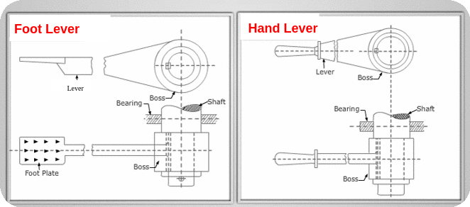
Diagram and Notations
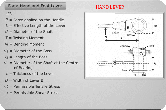
Step 1 :Design Of shaft and Boss :( )
)
1) Diameter of shaft d {subjected to torque only}
Torque Acting on Shaft
T= P ![]() L
L
Diameter of Shaft obtained on basis of shear stress
![]()
Find diameter of shaft d using this equation
2) Diameter of shaft at centre of bearing d1 {Subjected to torque and Bending moment}
Bending Moment acting on shaft
M = P ![]() l
l
Equivalent torque acting on shaft
![]()
![]()
Diameter of Shaft at centre of bearing on the basis of shear strength
![]()
![]()
Find diameter of shaft d1 using this equation
3) Dimensions of Boss (Which holds the shaft)
![]()
![]()
![]()
![]()
Step 2 : Design Of Key :
-
Using a square Key
![]() ,
,![]() ,
,
Shear Failure of key
![]()
![]()
![]()
![]()
Find lk using eqn. above
Step 3 : Design Of cross-section of lever ( B,t )
-
Using bending equation ,
![]()
![]()
Using this equation find B and t of lever.{Assume B=3t or any other relation given in problem}
-
The lever is subjected to bending moment,
M= ![]()
-
Moment of inertia
![]()
![]()
-
 Allowable stress for lever material
 -
Distance of extreme fiber form N-A
![]()
![]()
Steps in Short
Part |
Failure |
Equation |
To find |
|
Shaft {d,d1}
|
Torsional shear stress
Torsional shear stress |
T= P
M = P
|
d=
d1= |
|
Boss {d2,l2} |
Emperical relations |
|
d2=
l2= |
|
Key {Wk,tk,lk} |
Emperical relation {sq key}
Shear Failure of Key |
|
|
|
Lever Cross section {t,B} |
|
M=
|
t= B= |
B) Problems on Hand lever and foot Lever design
1) Design a foot lever, which is 1000 mm from the centre of shaft to the point of application of 800 N load. Find: Dimensions of rectangular arm of the foot lever at 60 mm from the centre of shaft assuming width of the arm as 3 times thickness. The allowable tensile stress may be taken as 73 N/mm 2 .
2) The effective length of hand lever is 1 meter. The effective overhang from the nearest bearing is 150mm. The lever and shaft are made of alloy steel for which tensile yield strength is 460N/ . If the maximum force exented at the handle is 300N, design the lever and the shaft with a safety with a safety factor of 4.
Ans: 1) d = 30mm, 2) = 48mm, 3) = 46.5mm 4) = 30mm, 5) b = 12mm, h = 36mm 3.
3)A hand lever for a brake is 0.8 m long from the centre of gravity of the spindle to the point of application of the pull of 300 N. The effective overhang from the nearest bearing is 100 mm. If the permissible stress in tension, shear and crushing is not to exceed 66 MPa, design the spindle, key and lever. Assume the arm of the lever to be rectangular having width twice of its thickness.
Links to other Topics in Machine design I
Machine Design I - Introduction to Design : Theory Q&A
Machine Design -I -Design of joints : Theory Q&A
Knuckle Joint : Design Procedure,Problems and Questions
Design of turnbuckle : Design steps, Problems and Question
Design of Levers : Hand Lever, Foot Lever, Bell crank lever
Design Of Bolted and Welded Joints
Design of Shafts: Theory and Numerical Problems
Couplings : Design Procedure and Numerical problems
Design Of SPRINGS : Questions and Numerical problems
Power Screw Design
Belt drives:Theory Q&A and Selection of Flat and V belts
- Log in to post comments