Machine Design I
Design of Joints : Knuckle Joint, Cotter Joint and Turn Buckle
Theory Questions and Answers
Q.1) State applications of Cotter Joint, Knuckle joint and turn Buckle
Knuckle Joint:
1) It is used as joint between the tie bars in roof trusses.
2) It is used in structures in suspension link.
3) It is used in for coupling trolleys with tractors.
4) It is used in chains, roller chains.
5) It is used in fulcrum for the levers
Cotter Joint :
1) It is used in bicycle for connecting pedal to sprocket wheel.
2) It is also used for connecting piston rod and the cross-head of steam engine.
3) It is used for connecting piston rod with the tail or pump rod
4) It is used in Foundation bolts.
Turn Buckle:
1) It is used in tie rod in overhead crane
2) It is used in electric poles to support them from ground.
3) It is used in long telegraph wires.
4) it is used in automobile chassis as an adjustable joint.
5) It is used in railway track changing mechanisms
Q.2) What is a Cotter ? Why taper is provided on cotter? How much taper is provided?
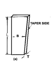
Cotter is a flat wedge shaped partl which is used to connect two rods which transmit the force/motion but without rotation. Cotter is fitted in the tapered slot and remains in its position by wedge action.
Because of taper,
i) It is easy to remove the cotter & dismantle the joint
ii) It ensures tightness of the joint in operation & prevents loosening of the parts.
Value of taper on cotter is 1 in 48 to 1 in 24.
Q.3) Differentiate between Key and Cotter
The main difference between keys and cotters are as follows:
(a) Keys are driven parallel to the axis whereas cotters are driven perpendicular to the axis.
(b) Keys are used in parts subjected to torque whereas cotters are used in parts subjected to tensile or compressive force.
(c) Keys resist shear over a longitudinal section whereas cotters resist shear over two transverse sections.
Q.4) Why the cotter in a cotter joint is kept weakest?
Ans : The cotter is the least material component (cheapest) in whole cotter joint, as well it is easy to replace on failure, so it is kept weakest in the joint.
Q.5) Differentiate between Knuckle joint and cotter joint (Four points)
Ans :
| Sr.No | Knuckle Joint | Cotter Joint |
|---|---|---|
| 1 | Can take only tensile load | Can take tensile and compressive load |
| 2 | Can permit angular movement between rods | Cannot permit angular movement. |
| 3 | Subjected to bearing failure | Not subjected to bearing failure |
| 4 | No taper or clearance provided | Taper or clearance provided |
| 5 | Applications : Tie bar, links of bicycle chain, joint for rail shifting mechanism | Applicaiton : Cotter foundation bolt, joining two rods with a pipe, joining piston rod with cross head. |
Q.6) State the advantages of Knuckle joint.
Ans : 1) Simplicity : The joint is relatively simple to design and manufacture.
2) Reliability : Since the joint consists of very few parts, it is more reliable.
3) Simple assembling and dismantling : It is very easy to assemble and dismantle, by just removing lockpin,collar and then separating two rods.
Q.6) State the advantages of cotter joint.
Ans : 1) Easy assembling and dismantling: It is assembled by hammering in the cotter and dismanteled by removing cotter.
2) Strong grip froce: Due to wedge action there is very strong tightening force which prevents loosening mf parts.
3) Simple to design and manufacture.
Q.7) Specify the change that must be made so that a knuckle joint can carry some compressive load alongwith tensile load?
Ans : Knuckle joint can bear compressive load only if the rods are properly guided, means if the angular movement of rods is prevented by some means then only it can take the compressive load.
But in case of cotter joint there is no possibility of angular movement between the rods hence it can naturally take the tensile as well as compressive load.
Q.8) Draw a neat labled sketch of Knuckle joint? List its various elements and state their functions.
Ans : The following diagram shows the assembled Knuckle joint,
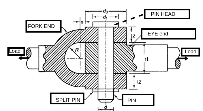
Following are the important components and their functions ;
1) Fork end : This is the modified end of the rod to be connected. It has two eyes, which have hole in them to accomodate the pin.This is also called double eye end.
2) Rod end : This is the another modified end of the rod to be connected. it has one eye, which has a hole of size equal to that of pin. This is also called single eye end.
3) Pin ; Pin is the connecting element between the two rods. It is held by both rods. It has a head provided for resting purpose. Its lower end has a small hole to accomodate the split/taper pin.
4) Collar and split/taper pin : Bottom part of pin is covered by collar and locked by taper/split pin, so that pin may not come out of joint. The function of split pin is to hold the pin in its place and avoid loosening of joint due to vibration.
Q.9) Draw a neat labled sketch of Cotter joint? List its various elements and state their functions.
Ans : The following diagram shows the assembled cotter joint,
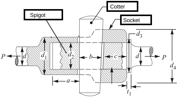
A cotter joint consists of following elements,
1) Spigot end ; This is the modified end of the rod to be connected by the cotter joint. It is in the form of enlarged cylinder with a rectangular slot in it.The slot is provided to pass the cotter through it . This is the male part of the joint. It also has a collar which rests against the coller of socket.
2) Socke end : This is the modified end of the rod to be connected by the cotter joint. It is hollow cylinderical in form and has an enlarged diameter collar. This also has a rectangular slot to accomodate the cotter in it. This is the Female part of the joint.
3) Cotter ; Cotter is the connecting element of the joint like pin in the cotter joint. The pin is a rectanular wedge shaped piece of metal. The cotter has taper on one side of it, to facilitiate the removal of cotter and for wedge action.
Q.9) Draw a neat labled sketch of Turn buckle?
Ans : The following diagram shows the assembled turn buckle,

It simply has threaded ends of two rods which are to be connected with an adjustable joint. One is threaded left hand threads and other is threaded with right hand threads. And a coupler nut which conncets two rods as shown in figure above. When the coupler is rotated in one direction it brings the both rods closer and vice versa.
--------------------------------------------------
Links to other Topics in Machine design I
Machine Design I - Introduction to Design : Theory Q&A
Machine Design -I -Design of joints : Theory Q&A
Knuckle Joint : Design Procedure,Problems and Questions
Design of turnbuckle : Design steps, Problems and Question
Design of Levers : Hand Lever, Foot Lever, Bell crank lever
Design Of Bolted and Welded Joints
Design of Shafts: Theory and Numerical Problems
Couplings : Design Procedure and Numerical problems
Design Of SPRINGS : Questions and Numerical problems
Power Screw Design
Belt drives:Theory Q&A and Selection of Flat and V belts
Power Screw Design
Belt drives:Theory Q&A and Selection of Flat and V belts
- Log in to post comments