Theory Questions and Answers
Q.1. What is the function of gearbox in a machine tool? or What is the need of a multispeed bearbox in a machine tool or automobile?
Ans : Following are the objectives that a gearbox is needed in a machine tool or gearbox
1) Adapting Power : The form of power (Speed and torque) provided by the source(primemover) is most of the times different than that of Consumer. So we need to change the torque and speed to suit the final requirements of the machine tool. This function is achieved by the gearbox. Gearbox either reduces speed and increases the torque or viceversa as per the requirement. A gear box is anologous to the ‘Transformer’ in case of electric power, which changes the voltage and current as per the requirement of the consumer.
2) Convert standard input speed to required output speed : Most industrial primemovers are motors which are manufacutred to give a standard speed output. The function of gearbox is to change that speed and make it suitable for a particular output.
3) Single speed primemover to multispeed output : Most primemovers have a constant single speed, the gearbox serves as a device which converts a single speed into multispeed drive.
4) Use small primemover for high torque application : Some applications need very high force at small velocity, in other words there is high torque requirement at very small rpm. Now if we decide to choose a primemover on the basis of torque requirement only, the primemover in market ot give that torque will be very bulky and costlier, here the gearbox speed reducer comes to rescue, the gearbox reduces the speed and increase the torque (in that proportion ) and we can use a normal prime mover for high torque applicaitons.
5) Gearbox as a connector : In some application the location of output shaft and location of primemover has space constrains. In that situation the gearbox acts as a connector between two shafts.
Q.2. What are the basic consideration in design of Multispeed gearbox?
Ans : Following are the main consideration in designing multispeed gearbox,
1) Optimum Speed Steps : The total speed range should be divided into optimum number of steps with suitable increment such as 10% to 20%.
2) No motor stoppage : The motor drive should not be stopped to change the speed.
3) There should be only one set of gears engaged to obtain the desired speed.
4) There should be minimum gears and other parts used to attain the required objective.
5) The gear control unit should be ergonomically designed and should be easily accesible and should not cause fatigue to operator.
6) No protruding parts : There should not be projecting or protruding parts from the gearbox, if possible it should be located inside the machine tool itself.
7) Direct switching : The gearbox should change to the required speed without passing through intermediate steps.
8) Maintainability : It should be easy to dismantle and replace the parts if required. It must be located in machine tool such that it will have easy access for maintenance.
Q.3. What are the various progressions for stepped regulation of speeds in machine tool gearboxes? State formula’s, advantages and limitations of each ? or Compare different laws of stepped regulations.
Ans : Following are the three laws of progression that can be used in machine tool stepped speed regulation,
1) Arithmetic Progression :
Arithmetic progression is a sequence of numbers in which each differs from the preceding one by a constant amount. Like 1,4,7,10,13 or 3,5,7,9 etc
Each next speed value is given by ,where
is the constant difference of arithmatic progression
maximum speed ,
minimum speed, z = number of steps in between max and minimum. If we use this progression considering a required cutting speed (m/min) and then found the range of diameter that can be machined , it becomes obvious that this progression is suitable in high spindle speed range and poor in low spindle speed range. Advantages : 1) Easy to calculate and understand. 2) Suitable in higher range of speeds { it gives good steps in higher range}. Disadvantage 1) Poor in low spindle speed range.
1) Harmonic Progression :
Harmonic progression is formed by taking reciprocals of arithmetic progression , like if ap is 1,4,7,10 … then hp will be 1/1,¼,1/7,1/10….
Harmonic progression is the modified form of arithmetic progression in which the difference between reciprocal of any two successive spindle speeds is constant. MathematicallyWhere C is a constant and any speed is given by
. If we use this progression considering a required cutting speed (m/min) and then found the range of diameter that can be machined , it becomes obvious that this progression is suitable in low spindle speed range and poor in high spindle speed range. Advantages : 1) Suitable in lower range of speeds . 2) Range of diameters is almost constant over given speed range. Disadvantage 1) Poor in higher spindle speed range. The speed steps in higher range are too wide.
NUMERICAL PROBLEMS ON DESING OF MACHINE TOOL GEARBOX

Following are the Numerical problems on Machine tool gearbox collected from prominent Universities,

1)  Draw the Symmetric Structure diagrams for following formulae and find out optimum formula from them and justify your answer
a) 2(1)2(2)3(4),
b)2(6)2(1)3(2) ,
c) 2(2)2(1)3(4)                                                                                                                                                {SPPU S-17}
2)  Design the four speed gearbox (design upto speed deviation diagram) for speeds ranging between 200 RPM to 820 RPM.
                                                                                                                                                                        {SPPU s-17}
3) A six speed gear box is required to be designed for a machine tool drive. The speed of spindle ranges between 200 rpm And 1200 rpm. If the gear box is driven by a motor having power rating of  8 KW and speed of  1200 rpm through belt drive. Draw the speed diagram and gearing diagram. Assumer suitable data if required
                                                                                                                                                                        {sppu S11}
4) A three stage, twelve speed gear box is required to be designed for spindle speed ranging between 60 r.p.m to 2880 r.p.m The second stage should consists of three speed steps. If the gear box is driven by an electric motor rating 5 kW  power and speed 1440 r.p.m.:
(i) Draw the ray diagram,
(ii) Draw the gearing diagram, and
(iii) determine the number of teeth on every gear.
Take same module for all the gears.                                                                                                              {sppu s13 }
5)  A multispeed gear box is required to be designed for a headstock of a turret lathe. It is required to have nine spindle speeds ranging from 60 rpm to 2880 rpm, if the gear box is driven by and electric motor having power rating  5 kW,  and speed 1140 rpm  ;
1) Draw the speed ray diagram,
2) Draw the gearing diagram,
3) Determine the number of teeth on each gear,
     Take same module for all gears.                                     {SUK w14,w12}
6) A multispeed gearbox is required to be designed for a small size gerneral purpose machine tool. It should have spindle speeds ranging between 100 rpm to 1000 rpm. If the recommended G.P. ratio is as per R5 series . Draw candidate structure diagram for machine tool gear box and select optimum structure diagram. Draw gear layout. Justify your selection {SUK s-13}
7) A three-stage, twelve speed gearbox is required  to be designed for spindle speed ranging between 50 rpm and 3000 rpm The second stage consists of three speed steps. If the gearbox is driven and electric motor having power rating 7.5 KW,1440 rpm electric motor.
1) Draw the speed and,
2) draw the gearing diagram
Take same module for all gears                                      {MU s16}
8) Draw the ray diagram and kinematic layout of a gearbox for completely geared headstock of a lathe. The range of speeds should be from 600 to 23 rpm respectively. Number of steps rquired are 12 and drive is from a 3 Kw motor running at 1440 rpm. {AU s14}
9) Draw the suitable speed diagram for a 14 speed machine tool gear box, which is having six speeds for high range operations with ceramic tools. The spindle speed range is from 160 rpm to 4200rpm. The gear box is driven by and electric motor having power rating 5KW and speed rating 1440 rpm.. {sppu s14}
10)  A two stage, nine speed gear box is connected to an electric motor running at 720 rpm through a belt drive. The gear box is required to have a minimum speed of 31.5 rpm and a maximum speed of 500 rpm. Using standard spindle speeds,
a) Draw the structure and speed diagram,
b) Draw  gear box layout,
c) Determine the number of teeth on each gear,
d) Draw percentage deviation diagram and check if design is within permissible limits.
e) Select diameter of pulleys for belt drive based on R20 series with diameter starting from 80mm diameter.                                         {sppu s15}
11) A machine tool requires 12 speeds in the range 1000 rpm to 180 rpm. List the most suitable speeds to be provided. Also draw ray diagram {sppu s16}
12) Decide the number of teeth of all gears from a 9 speed gearbox with speeds starting from 100 rpm and based on R5, to transmit 10KW power from a motor running at I 440rpm. (Assume that the minimum number of teeth in all stages is 20 and that the design is based on symmetric structure diagram only). Draw the deviation diagram of designed gearbox. Assume suitable data if necessary {sppu w13}
13)Draw Structure Diagrams for following structure formulae, find out optimum formula out of them and draw the gearing diagram for the optimum formula :
 2(3)3(1),2(1 )3(2),3(2)2(1), 3(1 )2(3),
                                                                                                                                                                               {sppu w13}
14) A multispeed gearbox is required to be designed for speed varying from 200 RPM to 2000 RPM. Recommended series is R5. It is to be driven by a motor running at 2880 RPM. Design the optimum gearbox considering. Symmetric Structure Diagrams. {sppu w14}
15) Draw the struture diagram and gear box arrangement for following equations of a six speed gear box :(i) z=2(1) 3(2), (ii) z=2(3) 3(1), (iii) z=3(1) 2(3) , (iv) z=3(2) 2(1). {sppu w15}
16) A three stage twelve speed gear box is to be used in machine tool for spindle speeds ranging between 25 rpm and 1500 rpm. The second stage of gear box consist of three speed steps. If the gear box is driven by 3.7 kW,750 rpm electric motor through the belt drive:
i) Draw the ray diagram and prepare the gearing diagram
ii) Determine maximum torque acting on shaft
The standard pulley diameters are:
80, 90, 100, 112, 125, 140, 160, 180, 200, 224,250, 280, 290, 300, 310,355, 375, 400, 450, 500mm                                                                                                          {sppu w16}
17) A machine tool requires six speed gear box. which having a 160 rpm minimum and 1000 rpm maximum speed, when the motor shaft speed is 1440 rpm. Draw structural diagaram. {sppu w16} 18) Figure below shows a sliding mesh gearbox in which input shaft pulley B, with 369 mm diameter, is driven by belt drive . Motor is running at 1440 rpm and pulley A has diameter 208 mm. Number of teeth on each gear is mentioned in the diagram. Study the diagram carefully and answer the following questions.
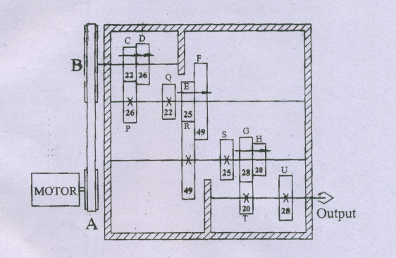
a) Find out all output speeds. b) Draw Speed diagram c) What is structure formula of this setup? d) What will be output speed if gear F is engaged with S and position of other sliing gears remains unchanged e) How the gear meshing should be, if we want to get output speed second from top ? f) What is the range ration of this gearbox.
- Log in to post comments