Explain intercooling and reheating in gas turbine with the help of T-S diagram.
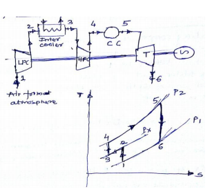
 LPC – LOW pressure cylinder HPC – high pressure cylinder CC – combustion chamber T – Turbine ( 2+ 2 marks) The net work of gas turbine cycle may be increased by saving some compression work. This is done by using several stages of compression with inter cooling of air between stages. The air from first stage of compression is cooled in inter cooler approximately to its initial temperature before entering to second stage of compressor. The effect of inter cooling is to decrease the network and increase the efficiency as compared to the simple ideal cycle without inter cooling. The ideal open gas turbine with inter cooling can be shown as 1 – 2 – 3 – 4 – 5 – 6 In first stage compressor atmospheric air is compressed from P1 to P2, it is them cooled from temperature T2 to T3 = T1 in the inter cooler at constant inter mediate pressure Px and finally compressed from Px to P2 in second stage or compressor.
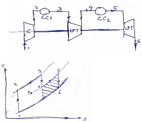
ii) Gas turbine with reheatingCC – Combustion Chamber C – Compressor

By reheating or adding heat to exhaust gases after have passed through a part of the rows of turbine balding (or stages), a further increase in work done obtained. In reheating, the gas temperature which has dropped due to expansion is brought back to approximately the initial temperature for expansion in next stage. Since the working fluid contains about 85% of air, additional fuel can be burnt by injecting it into the gases without any additional air supply. The reheat cycle can be shown as 1 – 2 – 3 – 4 – 5 – 6. The combustion gases from combustion chamber CC1 at temperature T3 is partially expanded in the HP turbine from P2 to intermediate pressure Px. After this, it is them passed through combustion chamber CC2 where it is reheated at constant pressure Px so that the temperature of gas is raised from T4 to T5. After this gas is expanded in second stage of turbine reheating is shown by shaded area
