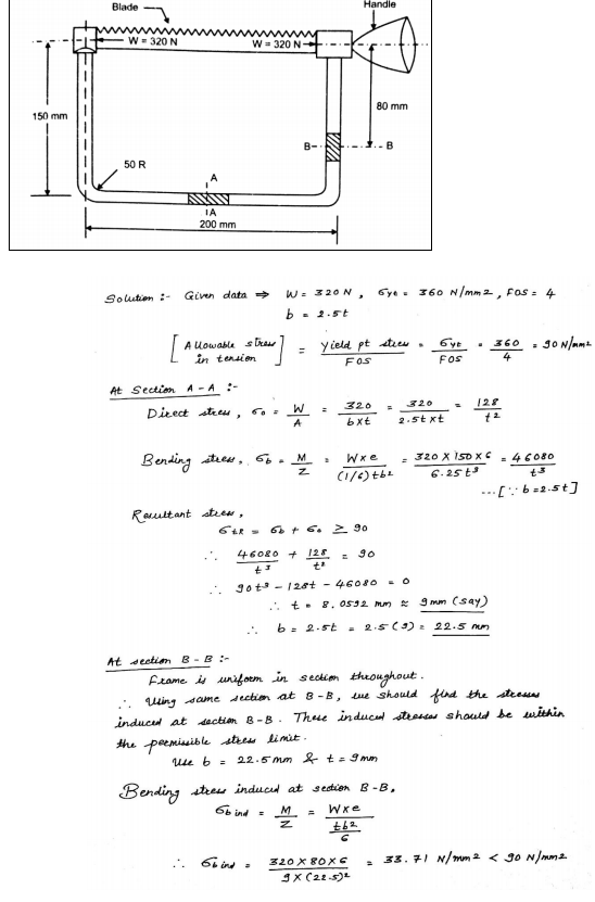
Fig.1Show of hacksaw The belt is assembled with tensoion
The following steps must be adopted in selecting the bearing from the manufacturer’s catalogue: 1. Calculate the radial and axial load reaction (Fa and Fr) acting on the bearing. 2. Decide the diameter of the shaft on which the bearing is to be mounted. 3. Select the proper size of bearing suitable for given application, specified with speed and available space. 4. Find the basic static rating Co of the selected bearing from the catalogue. 5. Calculate the ratio (Fa / VFr) and (Fa / Co). 6. Find the value of x and y i. e. radial and thrust factor from the catalogue.
The different areas covered under the ergonomics are: 1. Communication between the man (user) and the machine. 2. Working environment. 3. Human anatomy and posture while using the machine. 4. Energy expenditure in hand and foot operations. Communication between man and machine The machine has a display unit and a control unit. A man (user) receives the information from the machine display through the sense organs. He (or she) then takes the corrective action on the machine controls using the hands or feet.
Theories of Failures
Maximum shear stress theory is explained below
The principal theories of failure for a member are as follows:
(i) Maximum principal or normal stress theory
(ii) Maximum shear stress theory
(iii) Maximum principal or normal strain theory
(iv) Maximum strain energy theory
(v) Maximum distortion energy theory
Maximum normal stress theory (Maximum principal stress theory or Rankines theory
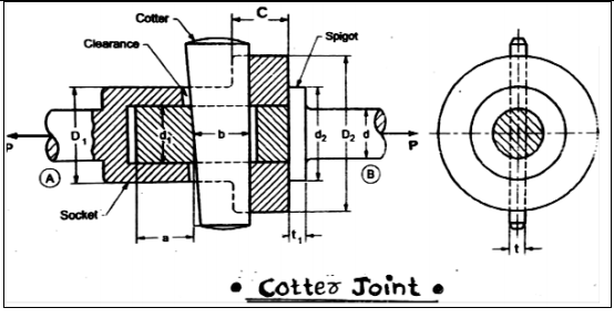
It consist of 3 elements: i. Socket ii. Spigot iii. Cotter Where, d= End diameter of rod d1= Diameter of spigot/Inside diameter of socket d2= Diameter of spigot collar D1= Outer diameter of socket D2= Diameter of socket collar C=Thickness of socket collar t1= Thickness of spigot collar t= thickness of cotter b= Mean width of cotter a= Distance of end of slot to the end of spigot P= Axial tensile/compressive force σt , σc , τ= Permissible tensile,
A good coupling should have the following requirements: (i) It should be easy to connect and disconnect. (ii) It should transmit the full power from one shaft to another shaft without losses. (iii) It should hold the shafts in perfect alignment. (iv) It should reduce the transmission of shock loads from one shaft to another shaft. (v) It should have no projecting parts
(i) Industrial and automotive gear boxes. (ii) Electric motors and machine tool spindles. (iii) Small size centrifugal pumps. (iv) Automobile front and rear axles
i) Cylinder head of the engine. (ii) Machine foundation. (iii) Assembly of fan, couplings. Any two examples (iv) Connect two bogies of the train with the turn buckle. (v) Structural bridges, pressure vessels, fly press (vi) Assembly of crank shaft and connecting rod.
(i) Sunk key: Rectangular sunk key, Square sunk key and Parallel sunk key (ii) Gib-head key (iii) Feather key Any four (iv) Woodruff key types of keys (v) Saddle key: Flat saddle key, Hollow saddle key (vi) Tangent key (vii) Round key