Key Points to remember
- A power screw is a device which is used to convert rotary motion into translatory motion and thereby transmitting power. Typical applications involve screw jack,fly press, C clamp,testing machines, lead screw of lathe machine and many other machine tool applications.
- Basically screws serve two purposes in our day to day life, first is FASTENING ( to hold two parts together) and second one is POWER TRANSMISSION (To transmit force and motion). As the name of this chapter suggests we will confine our discussion to the latter application of the screw.
- Basically a power screw is an inclined plane, which lifts load by application of suitable effort, each thread turn is an inclined plane which raises the load by a distance equal to the pitch of screw.
- Power screws provide very large mechanical advantage, best example of this is the Screw jack used for lifting heavy automobile with effort of a person.
- Power screws are mostly self locking,i.e. they retain their load at their position even when the effort is removed.
- Square threads and trapezoidal threads are two popular thype of threads used in power screws.
- Trapezoidal threads have more strength than square threads.
- Multistart threads are used when more distance is to be moved in one revolution of screw.
- The friction between screw and nut is responsible for rapid wear of the softer part of two, generally nut is made softer as it is economical to replace it.
- Screw is subjected to direct compressive stress as well as shear stress. If the length of screw is more and it is in vertical position it may subjected to buckling failure also.
- To reduce the friction beween screw and nut a recirculating ball screw is used in which sliding contact is converted into rolling contact.
Theory Questions and Answers on Power Screw Design
Q.1. State the advantages and disadvantages of using Power Screw for power transmission?
Ans : Following are the advantages of power screw
- Power screw can transmit large power and takes a very small space.
- Power screw can take higher loads.
- Power screw provides large mechanical advantage, due to which a small effort does a big task.
- Power screw provides accurate linear motion.
- Power transmission through power screw is smooth and noiseless
- Power screws are mostly self locking. i.e. they hold the load at their position even after the effort is removed. Example Screw jack used in automobiles.
- Power screws are simple to design, manufacture,assemble, maintain and are relatively low in cost.
Following are the disadvantages of power screw
- Power screws have very less efficiency i.e. about 30-40%.
- Rapid wear due to high friction between mating parts.
- Power screws can not be used for high speed power transmission, they are suitable for intermittent motion as slow speed.
Q.2. What do you mean by self-locking and overhauling screw?
Ans : The formula for torque required to lower the load in power screw is given by the relation,
where
W= load on screw, =Angle of friciton,
= Screw helix angle, d= mean diameter of screw
Now here are two possible situation resulting from the numerical values of and
1) >
{Friction angle greater than Helix angle}
In this case the value of Torque required to lower the load will be positive, means torque is required to be applied to move the load down. Means load will not come down by itself, Such condition is called Self locking condition. Such screw is called SELF LOCKING SCREW. Self locking of screw is not possible when the coefficient of friction is low or the lead of screw is large. Self locking condition is desirable in certain applications like Screw Jack.
2) <
{Friction angle less than Helix angle}
In this case the value of Torque required to lower the load will be Negative, means torque is not required to be applied to move the load down. Means load will come down by itself, Such condition is called Overhauling and such screw is called overhauling screw. This situation is to be avoided in design of screws which lift the load.
Q.3. What are various forms of threads used in power screws?
Ans : Following are the commonly used thread forms in power screws,
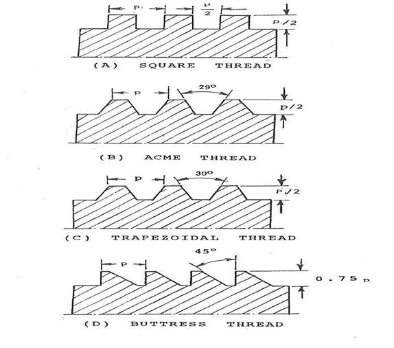
As shown in diagram above the power screw can have Square threads, Trapezoidal threads, Acme threads or Buttress threads.
Square threads have more efficiency, as well as there is no radial pressure on nut. But the square threads are difficult to manufacture and their strength is less as compared to the trapezoidal thread, because the thickness at the core is less.
Trapezoidal threds are mostly manufactured by milling process and hence economical to manufacture.They are stronger than the square threads. They have included angle as 300.
Acme threads are modified trapezoidal threads there the thread angle is 290 instead of 300. All other parameter are same for both types of threads.
Buttress threads combine the advantages of both square and trapezoidal threads. The axial wear can be compensated by means of split type nut.
Numerical Problems on Power Screw Design
1)  A two start trapezoidal is used in a screw jack to raise a load of 300kN. The screw has nominal diameter as 90mm, pitch as 12mm and helix angle (half thread angle) of 15°. Coefficient of friction is screw thread is 0.15. neglecting collar friction
calculate:  1) Torque required to raise the load
                   2) Torque required to lower the load
                  3) Screw efficiency                                                                                                                                                          {SPPU S-13}
2)  A 26 × 5 square threaded, single start power screw is used to support a load of 12 KN. The effective diameter of the collar is 46 mm and the coefficient of friction is 0.15. The nut is made of phosphor bronze having 0.12 as coefficient of friction and 6 MPa as allowable bearing pressure. The length of the handle is 300 mm. Calculate :
i) The force required to raise the load.
ii) The force required to lower the load.
iii) The yield strength of material for a factor of safety of 4.
iv) The overall efficiency of the screw.
v) The number of threads in nut.                                                                                                                         {SPPU W-15}
3) For a tripplestart screw nominal diameter is 50 mm and pitch is 8 mm. The load on screw is 7.5 kN and coefficient of friction is 0.12, Neglecting collar friction and asssuming length of nut as 48 mm , determine maximum stress developed in the screw body. Determine stress for screw and nut threads and bearing pressure, State whether the scew is selflocking or overhauling. {sppu S11}
4) A power screw having double start square threads of 25mm nominal  diameter and 5mm pitch is acted upon by an axial load of 10KN. The outer and inner diameters of screw collar are 50mm and 20mm respectively. The coefficient of thread friction and collar friction may be assumed as 0.2 and 0.15 respectively. The screw rotates at 12rpm. Assuming uniform wear condition at the collar and allowable thread bearing pressure of 5.77N/mm2, find:
i) The torque required to rotate the screw
ii) The stresses in screw, and
iii) The height of nut                                                                                  {sppu s15 }
5) A nut from a screw-nut combination, having double start square threads of 25 mm nominal diameter and 5 mm pitch, is acted upon by an axial load of 10 kN, against the direction its linear motion. The outer and inner diameters of screw collar are 50 mm and 20 mm respectively. The coefficient of thread friction and collar friction are 0.2 and 0.15 respectively. The screw only rotates at 12 rpm speed while the nut only translates. Assuming uniform wear condition at collar and allowable bearing pressure of 5.77 N/mm2, find:
a) Torque required to raise the load
b)Torque required to overcome collar friction
c) Total torque
d) Power required to rotate the screw
e) Stresses in screw body
f)Stresses in screw threads
g) Number of threads of nut in engagement with screw.                                             {sppu s16}
6) A machine vice as shown in Figure 2 has single start, square threads with 22 mm nominal diameter and 5mm pitch. The outer and inner diameters of the friction collar are 55 and 45 mm respectively. The coefficient of friction for thread and collar are 0.15 and 0.17 respectively. The machinist can comfortably exert a force of 125 N on the handle at a mean radius of 150 mm. Assuming uniform wear for the collar, calculate:
-
The clamping force developed between the jaws and
-
Overall efficiency of the clamp {sppu s17}
7) The lead screw of a lathe has single-start ISO metric trapezoidal threads of 52 mm nominal diameter and 8 mm pitch. The screw is required to exert anaxial force of 2 kN in order to drive the tool carriage during turning operation. The thrust is carried on a collar of 100 mm outer diameter and 60 mm inner diameter. The values of coefficient of friction at the screw threads and the collar are 0.15 and 0.12 respectively. The lead screw rotates at 30 rpm. Calculate :

a) The power required to drive the lead screw and

b) The efficiency of the screw

Evaluate the results using uniform wear theory and uniform pressure theory.  {sppu w13}
8)A double threaded power screw with trapezoidal threads is used to raise the load of 300 kN. The nominal diameter is 100 mm and pitch 12 mm. The coefficient of friction at screw threads is 0.15. Neglect collar friction torque. Calculate

1) Torque required to raise the load

2) Torque required to lower the load

3) Efficiency of the system.

State weather screw is self locking or not.                                                      {sppu w14}
9) A power transmission screw of a screw press is required to transmit maximum load of 10 tonnes and rotates at 60 rpm. Trapezodial threads are mention in the table. The screw thread friction coefficient is 012. Torque required for collar friction and journal bearing is about 10% of the torque to drive the load considering screw friction. Determine screw dimensions and its efficiency. Also determine power required to drive the screw. Maximum permissible compressive stress in screw is 100MPa. {sppu w15}


10) A nut and screw combination having double start square threads nominal diameter 25 mm and pitch 5 mm sudjected to axial load of 1000 N. The outer and inner diameter of the screw coller is 50 and 20 mm respectively. The coefficient of friction for collar thread and screw thread are 0.15 & 0.2 respectively. The screw rotates at 12 rpm. Assume uniform wear condition, and allowable bearing pressure is 5.77 N/mm2. Determine,
i) Power required to rotate the screw
ii)Stresses in screw Body & threads
iii)No. of threads of nut in engage with screw.           {sppu w16}
11)It is required to design a double start screw with square threads for a C -clamp The maximum force exerted by the clamp is 5 KN. It is assumed that the operator will exert a force of 250 N at the ball handle of the hand wheel. The screw is made of plain carbon steel 45C8 (Syt=330N/mm 2 ) while the nut is made of grey cast iron FG200.The factor of safety is 2.5. The distance between axis of handle and nut surface in clamped condition is 275 mm. The mean collar diameter is 12.5mm.The coefficient of friction at screw threads and collar is 0.15 and 0.17 respectively. The permissible bearing pressure is 15 N/ mm2.Design the screw and nut for a C-clamp and determine the following parameters:
i) Standard dimensions of screw
ii) Stresses in screw body at two critical sections
iii) Height of nut
iv) Stresses in nut threads
v) Length of handle.
Standard dimensions of square threads(Normal Series)                                            {sppu w16}
Links to other Topics in Machine design I
Machine Design I - Introduction to Design : Theory Q&A
Machine Design -I -Design of joints : Theory Q&A
Knuckle Joint : Design Procedure,Problems and Questions
Design of turnbuckle : Design steps, Problems and Question
Design of Levers : Hand Lever, Foot Lever, Bell crank lever
Design Of Bolted and Welded Joints
Design of Shafts: Theory and Numerical Problems
Couplings : Design Procedure and Numerical problems
Design Of SPRINGS : Questions and Numerical problems
Power Screw Design
Belt drives:Theory Q&A and Selection of Flat and V belts
- Log in to post comments