Shaft Coupling Design :Theory Questions and answers and Numerical problems
Shaft coupling design article containg design procedure and numerical problems of different types of couplings commonly used.
Design of Flanged Coupling (Unprotected and Protected type)
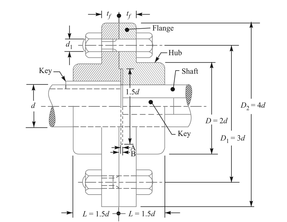
Notations used in design
d= Diameter of the shafts to be connected {Generally made up of steel}
D= Diameter Of hub {Hub and flange are one part but considered separated for failure {Generally made up of C.I}
D1= Pitch circle diameter of the Bolt circle
D2= Outer diameter Of the flange
L= Length of the flange
tf=Thickness of the flange
tp=Thickness of the protected portion.
dc=Core diameter of bolt {Threaded portion}
do= Outer diameter of bolt. {Threaded portion}
n=no of bolts connecting two flanges
t= thickness of the key
w=width of the key
l= length of the key
Design Steps
Step 1. To find torque acting on the shaft
Where OF is the overload or service factor, for example if the maximum torque is 20% more than mean torque then OF should be taken as 1.2 .
Using this formula the Toque acting on the shaft is calculated.
Step 2. To find diameter of shaft to transmit required torque
Use this equation to find the diameter of the shaft.
Step 3. Design of flanges
-
Emperical Relations
-
-
-
-
-
-
-
Check shear stress in hub
Find induced stress ![]() This should be less than allowable shear stress
This should be less than allowable shear stress ![]()
-
Check Shear stress in the Flange
Force = area resisting ![]() Stress
Stress
Find induced stress ![]() This should be less than allowable shear stress
This should be less than allowable shear stress ![]()
Step 4. Design Of Key
-
Empirical relation
![]() {if crushing stress is twice the shear stress}
{if crushing stress is twice the shear stress}
![]() and
and ![]() {if crushing stress is not twice the shear stress}
{if crushing stress is not twice the shear stress}
![]()
-
check shear stress induced in key
![]()
Find induced stress ![]() This should be less than allowable shear stress
This should be less than allowable shear stress ![]()
-
check crushing stress induced in key
![]()
Find induced stress ![]() This should be less than allowable shear stress
This should be less than allowable shear stress ![]()
Step 5. Design Of Bolts ![]()
-
No of Bolts
n=4 if diameter of shaft is upto d<55 mm
n=6 if diameter is between 55 <d< 150 mm
n=8 if diameter is above d>150mm.
-
Shear Failure of bolts
![]()
![]()
![]()
The bolt size should be rounded to nearest even number..
Steps In short :
|
Part |
Failure |
Equation |
To find |
|---|---|---|---|
|
Shaft |
Torque
Shear |
|
T=
d= |
|
Hub and flange |
Empirical relations
Shear Stress in hub
Shear Stresses in Flange |
|
Check
Check |
|
Key |
Empirical relation
Shear
Crushing |
|
Check Check |
|
Bolts |
No of bolts |
n=4 up to d= 55 mm n=6 d= 55 to d= 150 mm n=8 aboved=150mm |
Find n |
|
|
Size of bolt Shear |
|
Find dc
Find do |
NUMERICAL PROBLEMS :
- A rigid coupling is used for transmitting 20 kW power at 720 rpm. There are four bolts and the pitch circle diameter of the bolts is on 125 mm circle. The bolts are made up of plain carbon steel having ultimate tensile strength of 400 MPa . Determine the diamter of the bolts taking factor of safety as 3. Assume that there is no initial tightening load on bolts.
- A rigid type flanged coupling transmits 60 kW at 350 rpm. it has out diamter of flange as 250 mm and inner diamter as 200 mm. The bolts are six in numbers and are maded up of steel having 380 MPa . Taking factor of safety as 3, determine the size of bolts.
- A rigid coupling transmits 35 kW at 180 rpm . The service factor for the application is 1.5 ( take design torque as 1.5 times the mean torque ). Select the suitable material for the various parts of the coupling. Take the material for shaft as 40C8 ( syt= 380 MPa), material for bolts is 30C8 ( 400 MPa) and flanges are madeup of cast iron FG 150 ( Sut =150 MPa). Take factor of safety as 2.5 for all components. Also draw neat sketch of the coupling.
- A protected type flanged coupling is required to transmit 60 kw power at 1440 rpm. Design the coupling with following materials, Material for shaft material for shaft as 40C8 ( syt= 380 MPa), material for bolts is 30C8 ( 400 MPa) and flanges are madeup of cast iron FG 150 ( Sut =150 MPa). Take factor of safety as 2.5 for all components.
Links to other Topics in Machine design I
Machine Design I - Introduction to Design : Theory Q&A
Machine Design -I -Design of joints : Theory Q&A
Knuckle Joint : Design Procedure,Problems and Questions
Design of turnbuckle : Design steps, Problems and Question
Design of Levers : Hand Lever, Foot Lever, Bell crank lever
Design Of Bolted and Welded Joints
Design of Shafts: Theory and Numerical Problems
Couplings : Design Procedure and Numerical problems
Design Of SPRINGS : Questions and Numerical problems
Power Screw Design
Belt drives:Theory Q&A and Selection of Flat and V belts
- Log in to post comments