Shaft Design : Theory questions and numericals
Shaft design theory questions and answers : The theory questions on shaft design contain the various question and their answers related to shaft design.
Q.1. Distinguish Between Shaft, Axle and Spindle
Following table provides the difference
| Sr.No. | Shaft | Axle | Spindle |
|---|---|---|---|
| 1 | It is rotating element element of a machine | It is non-rotating or stationary element of machine | It is a circular component which revolves on something or something revolves on it |
| 2 | Shaft transmit torque as well as rotational motion | Axle is used to support the elements like wheels,pulleys,brake drums etc | Spindle is driving shaft, like spindle of drilling machine which carries the tool. |
| 3 | Shaft supports the driven member | Axle is only used as a load carrying member. | Spindle doesnot supports any other member |
| 4 | Examples :- Machine shaft, propeller shaft of automobile | Examples:- Front axle of automobile, Railway wagon axle which supports both wheels. | Examples: Lathe machine spindle, drilling machine spindle |
Q.2. 1) Give the Classification of shafts/What are different types of Shafts?
The shafts are classified in two typesas follows :
1. Transmission shafts: These shafts transmit power between the source and the destination (machines aborbing power). The counter shafts, line shafts, overhead shafts and all factory shafts are transmission shafts. Since these shafts carry machine parts such as pulleys, gears etc., therefore they are subjected to bending in addition to twisting. Transmission shafts are further categorized as,
- Axle
- Spindle
- Counter shaft
- Line Shaftis an example of machine shaft.
2. Machine shafts. These shafts form an integral part of the machine itself. The crankshaft of automobile is example of machine shaft or motor shaft is another example.
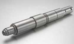
Q.3. What is the function of transmission shaft? Why the transmission shafts are stepped?
Ans : A transmission shaft has the function to support the transmission elements like gears, pulleys ,sprockets and also the bearings. Generally the transmission shaft is circular in crosssection which has keyway cut on it to accomodate the key in it. The transmission shafts are stepped to provide the shoulders for proper positioning of the transmission elements, the ends have minimum diameter to hold the bearings on two ends.
Q.4. What are the requirements of material for a shaft? What are the different materials used for shafts?
Ans : The material used for shafts should have the following properties :
1. Shaft material should have high strength.
2. Shaft material should have good machinability.
3. Shaft material should have low notch sensitivity factor.
4. Shaft material should have good heat treatment properties.
5. Shaft material should have high wear resistant properties.
General transmission shafts are made up of medium carbon steels such as 30C8 and 40C8.
When more strength is required one can go for high carbon steels such as 45C8 or 50C8.
Further alloy steels are also used for making transmission shafts 16Mn5Cr4,16Ni3Cr2,40Ni6Cr4Mo2. Alloy steels have higher in strength, hardness and toughness.
Commercial shafts are made up of low carbon steels .They are produced by hot-rolling and finished to size by cold drawing. Cold drawn shafts are stronger than hot rolled shafts.
Q.5. Why Hollow shaft is preffered over solid shaft? or What are advantages of hollow shaft?
The following are advantages :
- Low weight: for the same power to be transmitted and same material of both shafts, a hollow shaft is lighter than the solid shaft.
- Stiffness: for the same weight ,stiffness of hollow shaft is more than solid shaft, Stiffness is the resistance to bending.
- Natural Frequency : Natural frequency of hollow shaft is more than that of solid shaft with same weight.
- Low cost : The same power transmission can be done with less material so automatically cost of shafting reduces.
Q.6. Write a note on ASME code for shaft design
Ans : ASME code which was established in 1927, defines certain rules to be followed for shaft design, following are the important criterion as defined by code
- The permissible shear stress of the material will be given by the smaller of the two of the following values
where Syp is the allowable yield point, Sut = Ultimate tensile strength
2. If shafts have a keyway, or stress concentraton due to shoulder fillet then the permissible stress will be taken as 0.75 times the allowable stress obtained in above equation .( Means strength will be reduced by 25%)
3) To account for type of loading ASME code defined shock and fatigue factors as KB and KT for bending and torsion.
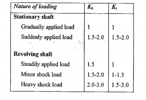
Design equation for solid shaft is on the basis of equivalent torque is given as ,
Similarly Permissible bending stress based on equivalent bending moment is given as ,
Q.6. Which stress is considered as basis for shaft design?
Ans : A shaft is subjected to torsional shear stress while transmitting power,so when there is no other load on shaft "Torsional shear stress" is considered as the design stress ans the torsional equation is used as basis for shaft design. When the shaft is subjected to bending moment in additiona to torsion, bending stress and torsional shear stress are considered as basis for the shaft design.
When the shaft is subjected to torsion,bending moment and axial force also then the combined principal stress is taken as basis for th shaft design.
NUMERICAL PROBLEMS ON SHAFT DESIGN
1) A shaft is supported by two bearings which are placed 1m apart. A 600mm diameter pulley is mounted at a distance of 300mm to the right of left hand bearing and this drives a pulley directly below it with the help of belt having maximum tension of 2250 N. Another pulley 400mm diameter is placed 200mm to the left of right hand bearing is driven with the help of electric motor and belt, which is placed horizontally to the right. The angle of contact for both the pulleys is 180° and coefficient of friction = 0.24. Determine the suitable diameter for a solid shaft, allowing stress of 42 MPa in shear for shaft material. Take the torque on one pulley is equal to that on the other pulley.
2) A shaft is supported by two bearings which are 1.3 m apart. A 750 mm diameter pulley is fixed at a distance of 400mm to right of LH bearing, this drives a pulley directly below it with belt drive having max tension 2.1 kN. Another pulley 500 mm diameter is placed to left of RH bearing which is driven by motor. Taking angle of contact 180° and coefficient of friction = 0.22 Determine the suitable diameter for a solid shaft, allowable stress of 50 MPa in shear for shaft material. Take the torque on one pulley is equal to that on the other pulley.
3)Figure shows shaft layout, supporting two spur gears B and C as shown in figure.The shaft is supporting by two bearings A and D. The PCD of gear A and B are 900 mm and 600 mm respectively. The material used
for shaft is steel with Sut - 770 N/mm 2 and Syt 580 N/mm 2 . The factors Kb and Kt of ASME code are 1.5 and 2.0 respectively, Determine the diameter of shaft according to ASME code. Consider the effect of Keyway.Total length of shaft is 2.7 m mm as shown in figure.

4) Design a hollow shaft having diameter ratio of 0.6.{Ratio of inner dia to outer dia}. It is supported on two bearings which are 500 mm apart and a spur gear is mounted on overhung of 500 mm from RH bearing. The gear is subjected to Horizontal tangential force of 5 kN and vertical force is 2 kN in magnitude. Using factor of safety 2.78 and power to be transmitted as 11 kW at 1000 rpm, take yield shear strength of material as 370 MPa. Use maximum shear stress theory of failure design.
5)A line shaft supporting a spur gear B and pulley D as shown in fig.1. The haft is mounted on two bearings A and C. The diameter of pulley and gear are 500 and 350 mm respectively . The pulleys transmit 20 KW power at 500 rpm to the gear: P 1 and P 2 are the belt tensions in the tight and slack sides. While P t and P r are tangential and radial components of the gear tooth force. Assume P 1 = 3 P 2 and P r = P t tan(20°). The gear and pulley are attached to shaft with keys. The material for the shaft is 50 C4 (Sut = 700N/mm 2 and Syt = 460N/mm 2 ) Determine the shaft diameter using ASME code if K b =K t =1.5

6) Determine the diameter below which the angle of twist of a shaft, and not the maximum stress, is the controlling factor in design of a solid shaft in torsion. The allowable shear stress is 55MN/m 2 and the maximum allowable twist is 0.3deg/m. (Consider a shaft has no keyway in it). G = 80 GN/m 2 .
7) A shaft is supported by two bearing placed 1.1 m apart. A pulley of diameter 620 mm is keyed at 400mm to the right from left hand bearing and this drives a pulley directly below it with a maximum tension of 2.75KN. Another pulley of diameter 400mm is placed 200mm to the left of right bearing and is driven with a motor placed horizontally to the right. The angle of contact of pulley is 180 degrees and the coefficient of friction between belt and the pulley is 0.3. Find the diameter of the shaft. Assume K b = 3, K t = 2.5 {for ASME code} , S yt = 190MPa, S ut = 300MPa.Also find the dimensions of a hollow shaft, having outer diameter of 80mm, for the same data. Also compare the weight of the solid shaft to hollow shaft.
8)A transmission shaft with the bearings 0.8 m apart receives 20KW power at 500rpm through a pulley 300mm in diameter and mounted at an overhung of 200mm. A 360 mm diameter pulley mounted midway between the bearings transmits the torque to a shaft located below it. Both the pulleys have vertical belt tensions and the coefficient of friction between the belt and pulley is 0.3. If the required safety margin is 3, design the shaft using maximum shear stress theory. Use the following properties for shaft material -
S ult = 700 MPa,
S yt = 460 MPa.
If the above shaft is replaced by hollow with the ratio of inner diameter to outer diameter as 0.6, calculate the ratio of weights of hollow shaft to solid shaft.
9) Discuss the design of hollow shaft on torsional rigidity basis. Using this basis evaluate the inside and outside diameters of the shaft for following
data
i) Power to be transmitted by shaft : 45 kW
ii) RPM of shaft : 500 rpm
iii) Ratio of inside diameter to outside diameter : 0.6
iv) Material of shaft :Carbon steel with ( τ all = 84 mpa).
10) A belt pulley is keyed to the shaft midway between the supporting bearings kept at 1000 mm apart. The shaft transmits 20 kW power at 400 rpm. The pulley has 400 mm diameter. The angle of wrap of belt on pulley is 180° and the belt tension acts vertically downwards. The ratio of belt tensions is 2.5. The shaft is made of steel having an ultimate tensile strength and a yield strength of 400 N/mm 2 and 240 N/mm 2 respectively. The combined shock and fatigue factors in bending and torsion are 1.5 and 1.25 respectively for ASME code. The permissible angle of twist in shaft is 0.25° per meter length and the permissible lateral defection is 1 mm per meter length. Design the shaft on the basis of
a) Strength
b) Torsional rigidity
c) Lateral rigidity Take G = 80×10 3 N/mm 2 and E = 200×10 3 N/mm 2
Links to other Topics in Machine design I
Machine Design I - Introduction to Design : Theory Q&A
Machine Design -I -Design of joints : Theory Q&A
Knuckle Joint : Design Procedure,Problems and Questions
Cotter Joint : Design Procedure,Problems and Question answer
Design of turnbuckle : Design steps, Problems and Question
Design of Levers : Hand Lever, Foot Lever, Bell crank lever
Design Of Bolted and Welded Joints
Couplings : Design Procedure and Numerical problems
Design Of SPRINGS : Questions and Numerical problems
Power Screw Design
Belt drives:Theory Q&A and Selection of Flat and V belts
- Log in to post comments