Theory questions and answers on SPUR GEARS
Q.1. State the applications of Gear drives?
Ans : Gear Drives are the positive drives {no slip} which are found in almost all complex machines and equipments. Gear drives transmit the power from one shaft to another shaft by means of engagement. They are found wide varier of applications where power is to be transmitted without any slippage and between two shafts which are close to each other. As well gears found application in changing the form of power (torque and speed). Means one can greately reduce the speed and as a result increase the torque or vice versa. Some common applications are,
-
Atutomobiles
-
Power plants (Electricity generation)
-
Machine tools
-
Material handling equipments
-
Rolling mills
-
Hand tools and equipments.
-
Printing machines
-
Sewing machines
-
Earthmoving and construction machinary
-
Air compressors and gear pumps.
-
Gear Trains for increasing or reducing speed.
-
Automation and robots.
Q.2. State advantages and disadvantages of Gear drive over other drives?
Ans : Gear drives offer following advantages over belt/chain drives
1. Constant Velocity ratio : It is positive drive (no slip), so its velocity ratio remains constant.
2.Compactness : For the required reduction/enlargement of speed the size of drive is compact as compared to chain/belt.
3.High Capacity : Since the power is transmitted by engagement (not by frictional grip) it can transmit huge power which is not possible for the belt or chain drive.
4.Shifting possibility : In case of gear boxex the ratio of drive can be changed without stopping the wheels by shifting mechanism, which is not possible in case of belt drives. Possible upto some extent in chain drives.
5.High efficiency : Gear drives have very high transmission efficiency as compared to others.
Gear drives have following limitations.
1. Distance limitations : Gear drives can not be used for long distance power transmission.
2. Precise alignment : Gear drives need exact and precise shaft alignments, they do not permit any misalignment which the belts do permit due to flexibility.
3. Manufacturing cost : Gear Drives are manufactured using sophisticated machines and tools, so their initial cost is high.
4. Maintenance : gear Drives Need proper lubrication and maintenance at regular intervals.
5.Noise and vibration : Any inaccuracy in manufacturing can cause vibrationas and noise during the operation.
Q.3. In a gear speed reducer, Why the diameter of an outpur shaft is greater than input shaft?
Ans : The function of a gear speed reducer is to change the form of the power from high speed low torque to the low speed high torque. In other words the gear speed reduces, increases the torque and reduces the speed.
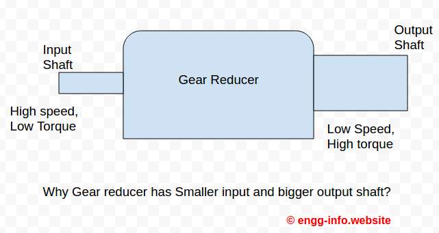
The size of the shaft is a function of the torque to be transmitted (and not the speed) , means to transmit more torque we need bigger shaft. Hence since in a gear speed reducer torque is more at output end hence it is of bigger size than input shaft.
Q.4. State the law of Gearing.
Ans : The Law of gearing states that,
The angular velocity ratio between tow gears of a gearset must remain constant throughout the mesh.
or in more technical terms
The common normal to the thooth profile should always pass through a fixed point called pitch point , in order to obtain a constant velocity ratio.
The gif image illustrates the exact meaning of the above statement.
 Image by : Claudio Rocchini ,Wikipedia
The gear tooth profiles shown above are the involute profiles. Blue arrow shows the contact forces between them. the force line (line of action of force) runs along the tangent common to both circles. This is what the law of gearing states.
Q.5. Why Involute curve is adopted for gear tooth profile? State advantages of both involute and cycloidal teeth gears or Compare Involute and Cycloidal gears
Ans : The involut curve is defined as,
The involute of a circle is the spiralling curve traced by the end of an imaginary taut string which unwinds itself from stationary circle called base circle.
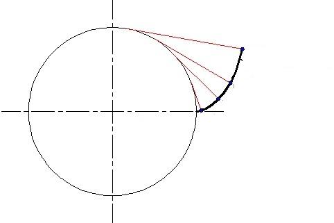
As shown above the involute gear profile is formed by the end of stdring. The reason for using the involute profile in gear is that in involute gear profile the contact between a pair of gear teeth occurs at a single instantaneous point where the two involutes of the same spirat mee each other.
Another Profile which satisfies the basic law of gearing is Cycloidal curve.
A cycloidal curve is formed when a circle rolls over another circle without slipping. When it rolls from outside the curve is called Epicycloid and when it rolls from inside it is called hypocycloid.
following are the two benefits of cycloidal gear tooth profile,
In involute profile the contact between two gears is over very small area which results in less wear strength, whereas in case of cycloidal gears there is large contact area between the two meshing gears which increases the wear strength.
There is no interference in case of cycloidal gears because convex flank of one tooth is in contact with the concave flank of mating tooth.
However the cycloidal profile is rarely used because of following two major disadvantages,
- Difficulty in Manufacturing : It is very difficult to manufacture the cycloid tooth profile because itconsits of hypocycloid as well as epicycloid curve at a time.
- Variable pressure angle : Cycloidal curves provide variable pressure angle where as the pressure angle in case of involute gears is constant.
Following table brings out the Difference
| Criterion | Involute Gear profile | Cycloidal Gear Profile |
|---|---|---|
| Pressure angle | High presssure angle but constant | Low Pressure angle but variable |
| Efficiency | Low Overall efficiency | High overall efficiency |
| Interference | Prone to interference | No interference |
| Error Tolerance |
Tolerant to minor error in centre to center distance |
Sensitive to Errors |
| Manufacture | Easy to manufacture | Difficult to manufacture due to dual arcs. |
Numerical problems on SPUR GEARS
1) It is required to design spur gear pair having 20 degree full depth involute teeth. The input shaft is rotating at 1000 revolution per minute and is receiving power 7500 Watts through a coupling. The output shaft is running at 500 rpm. Both gears are made up of steel having Ultimate tensile strength of 410 N/mm2. Assuming suitable number of teeth on pinion calculate 1) Module of gears (Assuming pitch line velocity of 5m/s for velocity factor calculation) 2) Buckingham Dynamic load and Factor of safety. Take , Service factor =1.25, Factor of safety 1.75, Grade for gears 6, Deformation factor 11400 N/mm2 ,,
,
2)  A pair of gears having 20 0 full depth involute profile consists of 2 teeth on pinion and 80 teeth on gear. Pinion is rotating at a speed of 1440 revolutions per minute. Power to be transmitted its 10 kW. Both pinion and gear are made up of steel having  ultimate tensile streneth of 660 N/mm2. The gears are heat treated to surface hardness of 350 BHN(Brinell Hardness Number). Calculate

1) Module of the gears using beam strength or wear strength

2) Calculate all essential dimensions of gears

3) Factor of safery for both beam and wear stength for your design

Assuming velocity factor accounts for the dynamic load, service factor=1.5, Initial factor of safety =1.75,

Lewis form factor
3) A pair of spur gears having 200 full depth involute profile consists of 19 teeth which mesh with 40 teeth gear. The pinion receives 7.5 kW at 1500 rpm. Taking service factor as 1.5. The pinion as well as the gear are made up of 40C8 grade steel having ultimate tensile strength Sut=600 N/mm2. Use the module as 4 and face width as 40 mm respectively. Determine the factor of safety, taking velocity factor to account for the dynamic load. 2) If the factor of safety is 2 for pitting failure, determine the hardness for the gears.
4) Determine the maximum power that the gears can transmit with the following data,

Gear profile : 200 full depth involute

No of teeth : on pinion: 20 , on gear  :41

Module : 3

Face width for gears : 40 mm

Ultimate tensile strength : 590 N/mm2

Surface hardness for gears  : 400 BHN

Pinion speed : 1450 rpm

Service factor for application : 1.75

Factor of safety : 1.5

Assume that velocity factor accounts for the dynamic load.
5) Find the rated power that can be transmitted in case of following pair of gears,

Pressure angle  : 200

No of teeth : Pinion = 25 teeth, Gear =60 teeth ,

Module : 5 mm,

Face width = 40 mm,

Speed of pinion : 500 rpm,

BHN : 200

Service factor  : 1.75

Factor of safety :  2

Assume that dynamic load is accounted through velocity factor.

Also determine wear strength and static load that gears can transmit safely.
6) A compressor is running at 300 rpm and is driven by a 7.5 kW,1200 rpm electric motor through a pair of gears. The central distance between gears needs to be 250 mm. The gears are made of 50C4 material having ultimate strength 700 MPa. Take service factor as 1.5, factor of safety as 2. Initially using the velocity factor to account for the dynamic load , 1) Design the dimensions of the gear 2) Assuming Grade 6 of manufacture and find the dynamic load using the Buckingham's eqn. 3) Determine the available factor of safety for the designed pair in bending. 4) Using the obtained factor of safety specify the required surface hardness for the gear surface. Make the use of following data : Pressure angle : 200 , Lewis form factor
- Log in to post comments