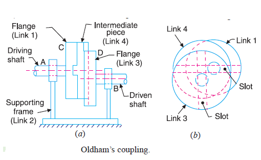
State inversions of double slider crank chain. Explain Oldham's coupling with neat sketch
Inversions of double slider crank chain:
i.Scotch Yoke mechanism.
ii.Oldham’s coupling.
iii. Elliptical trammel.
Oldham’s coupling:
An Oldham’s coupling is used for connecting two parallel shafts whose axes are at a
small distance apart. The shafts are coupled in such a way that if one shaft rotates, the other shaft
also rotates at the same speed. This inversion is obtained by fixing the link 2, as shown in Fig.
The shafts to be connected have two flanges (link 1 and link 3) rigidly fastened at their ends by
forging. The link 1 and link 3 form turning pairs with link 2. These flanges have diametrical slots
cut in their inner faces, as shown in Fig. The intermediate piece (link 4) which is a circular disc,
have two tongues (i.e. diametrical projections) T1 and T2 on each face at right angles to each
other. The tongues on the link 4 closely fit into the slots in the two flanges (link 1 and link 3).
The link 4 can slide or reciprocate in the slots in the flanges.

When the driving shaft A is rotated, the flange C (link 1) causes the intermediate piece
(link 4) to rotate at the same angle through\ which the flange has rotated, and it further rotates the
flange D (link 3) at the same angle and thus the shaft B rotates. Hence links 1, 3 and 4 have the
same angular velocity at every instant. A little consideration will show that there is a sliding
motion between the link 4 and each of the other links 1 and 3.
