Turnbuckle Design: Diagram, Steps and Numericals
Turnbuckle design introduction
Turnbuckle design is all about finding its dimensions to suit the application and its load conditions. A turnbuckle also called adjustable joint or bottle screw or stretching screw is mainly used for adjusting the tension or adjusting length in the cables, rods or tie rods. In its simplest form it has a frame having nuts at both ends in which the rods fit, roation of the frame brings the rods closer or farther. It is commercially with wide variety of end and adjustments. Following are the some of the illustrations.
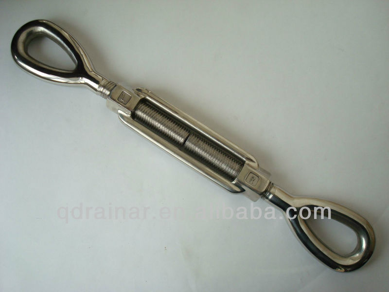
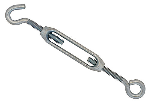
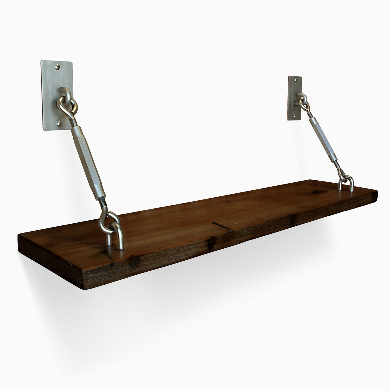
Commercially different designs are available for the turnbuckle, follwoing are the some of them,
Turnbuckle design: Constructional details
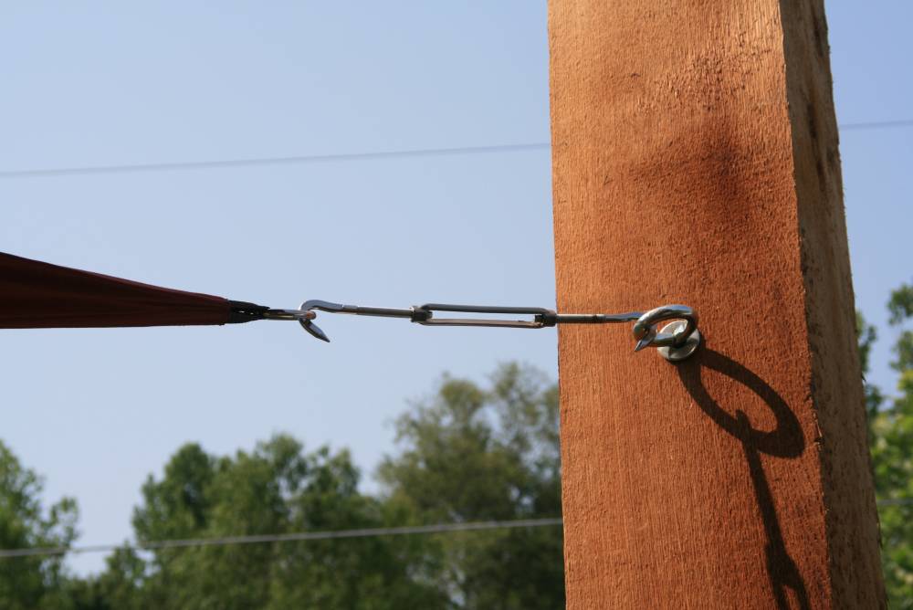
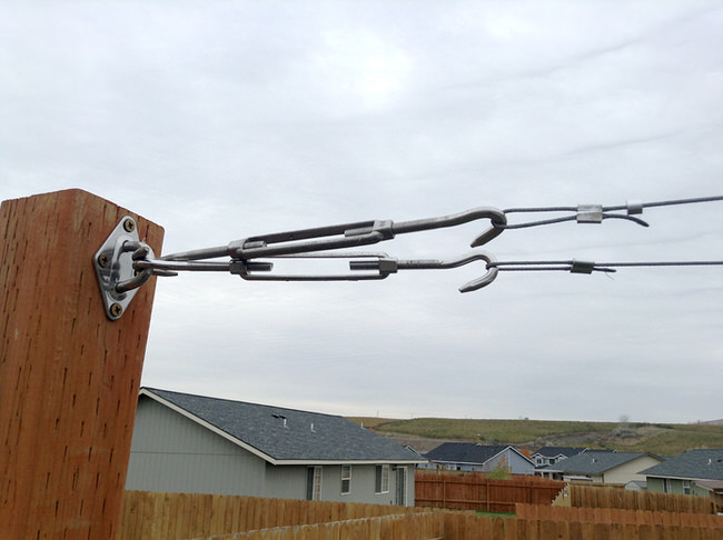
A trunbuckle is a static device which is used for adjusting tension at any cable, tie-bars,tie-ropes. Common applications are the ropes used for supporting power transmission cables belt tension adjustment in tie rods. It consists of a tubular body called coupler which is mostly cast steel. The central portion is hollow and at the ends there are two nuts in which the rods fit. Its exploded view is shown below,
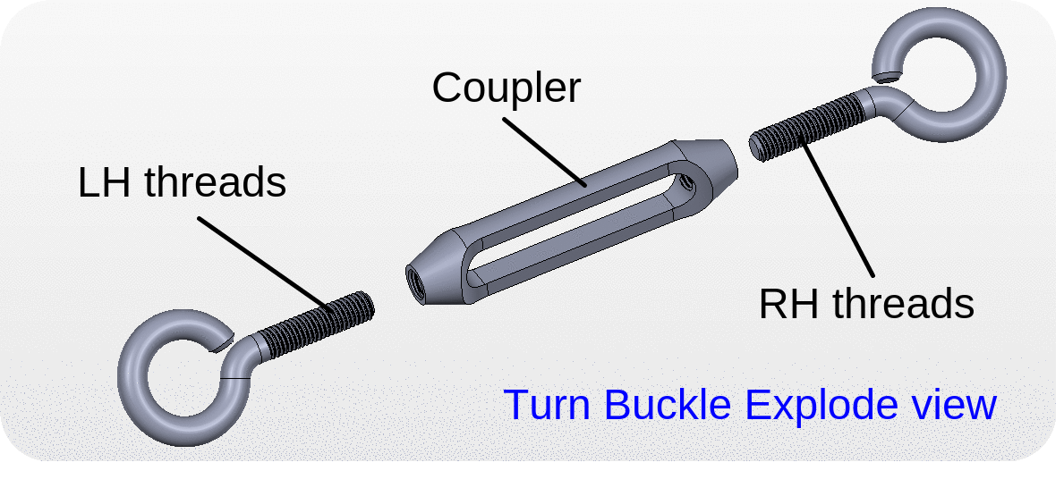
Since there are left hand and right hand threads due to which when the coupler is moved in one direction both rods move closer and viceversa.
Turnbuckle Design Steps
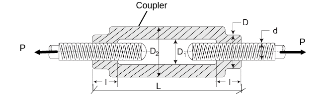
Notations used in Design,
dc = Core diameter of the rod (threaded portion), d = Outer diameter of rod (threaded portion), D = Outer diameter of coupler at end, D1 = Inner diameter of coupler at centre, D2 = Outer diameter of coupler at centre, l = Length of threaded portion, L = Total length of coupler.
Step 1. Decide the design Load (Pd)
For threaded portion the design load is taken 30% more than the given load to account for friction in threads
Pd=1.3 ![]() P
P
Step2. Design of tie rod (dc,d) -
*Tensile failure
Pd = Area x Stress
![]() Find dc.
Find dc.
*Outer diameter of threaded portion
d=1.19 * dc
Step 3. Design of coupler nut (l,D)
*Tensile failure of Coupler nut
![]() Find D
Find D
*Shear failure of threads
![]()
Find l
Step 4. Design of coupler (D1,D2,L)
*Empirical relation
![]()
*Tensile failure of coupler
![]() Find D2
Find D2
*Empirical relation
L=6d
Steps in short ( Tabular form)
|
Part |
Failure |
Equation |
To find |
|
Design load |
Empirical |
Pd=1.3 |
pd |
|
Design of rod (dc,d) |
Tensile
Empirical |
d=1.19 * dc |
dc
d |
|
Design of Coupler nut (D,l) |
Tensile
Shear |
|
D
l |
|
Design of Coupler (D1,D2,L) |
Empirical
Tensile
Empirical |
L=6d
|
D1=
D2=
L= |
Turnbuckle design :NUMERICAL PROBLEMS
1) Design a turnbuckle for a pull of 24 kN. Assume permissible stress at tension and shear as 100 MPa and 80 MPa. Assume standard proportions wherever necessary.
2) Design a turnbuckle to withstand a tensile load of 50 kN. Assume safe tensile and shear stress as 80 MPa and 60 MPa respectively. Also draw a neat dimentioned sketch of the joint.
3) The pull in the tie rod of a truss is 50 kN, is connected with adjustable joint (turn buckle). Design the adjustable joint taking the following values of permissible stresses,

Permissble tensile stress : 75 MPa

Permissible Shear stress : 40 MPa

Permissible Crushing stress : 100 MPa
4) A tie rod is subjected to a pull of 45 kN. Design an adjustable joint to take the load with following permissible stresses,

Allowable tensile stress : 56 MPa

Allowable Shear stress : 40 MPa

Allowable Crushing stress : 70 MPa
5) A turn buckle is subjected to a tensile load of 150 kN, Take the following allowable stresses,

Permissble tensile stress : 85 MPa

Permissible Shear stress : 60 MPa

Permissible Crushing stress : 140 MPa
Turnbuckle design :Theory question and answers
Q 1. List the uses of Turn buckle
Ans :Turn Buckle is generally employed as a length or tension adjusting element in an assembly. Following are the common applications found.
1) It is used in tie rod in crane
2) It is used in electric poles to support it.
3) It is used in telegraph wires
4) it is used in automobile chassis.
5) It is used in railway track changing mechanism.
Q 2. Why the threads on both sides of turn buckle have different hands ( why left handed and right handed threads are provided on two ends of turn buckle).
Ans :The main function of turn buckle is to adjust length or tension in two rods or ropes it connects. In order to acoomplish this function it must pull and push both rods when roatted. If we provide the sam threads on both ends of the turn buckle, it will just move over the threads and rods will neither pulled pushed. Because of privinding the opposite threads, when the turn buckle in rotated in one direction it pulls both the rods inside and when it is rotated in opposite direction it pushes away both rods. For this reason the turn buckle has different handed threads on its both ends.
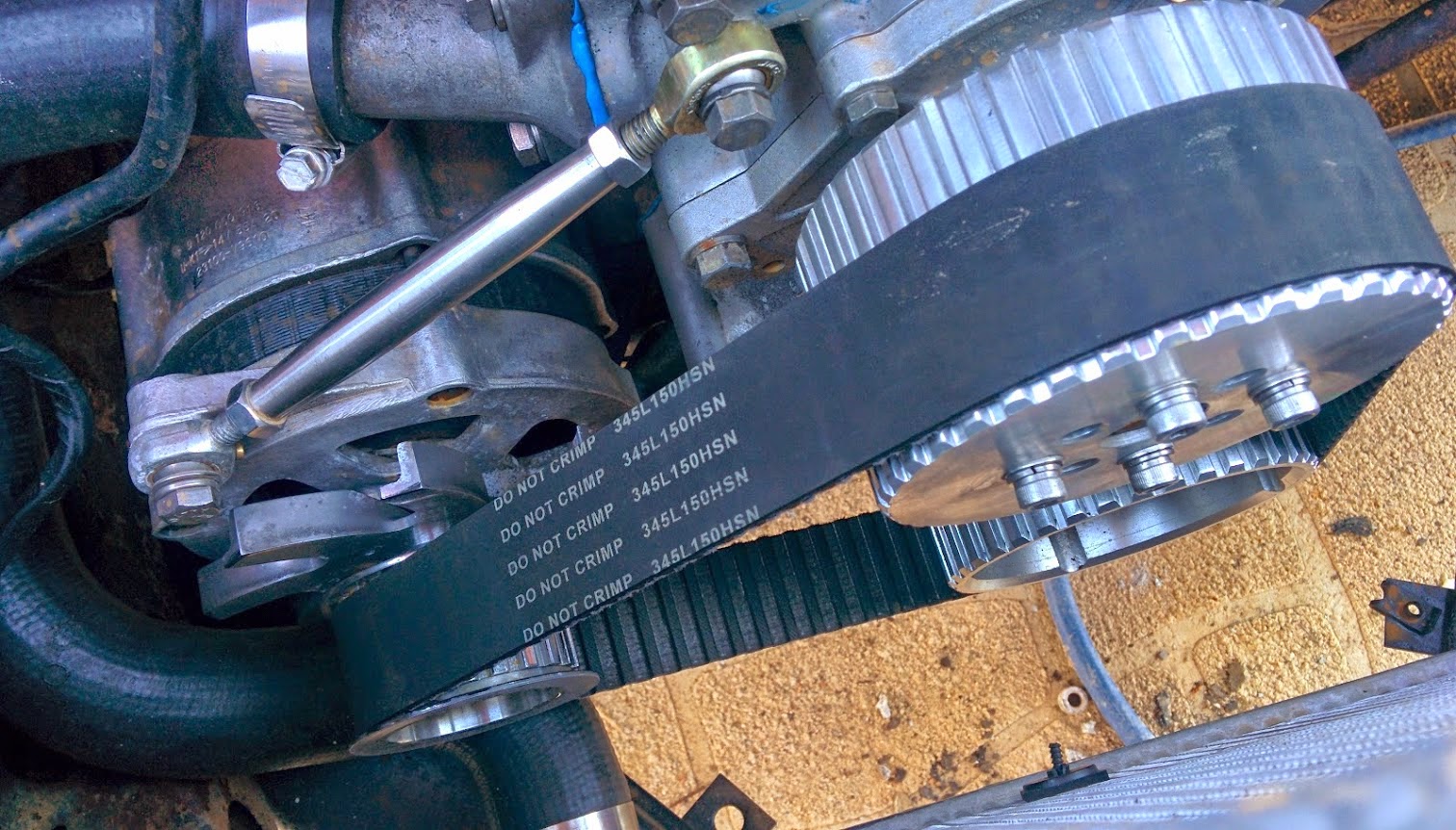
Q 3. How turn buckle is applicable in motored belt drives?
Ans : In case of motored belt drives, we need to adjust the belt tension as per requirement. In order to achieve this the turb buckle is employed between the two pulleys such that when rotated it increases or decreases the diatance between two pulleys and thus adjusting the tension of the belt.
Q 4. Draw a neat sketch of turnbuckle and show important dimensions?
Ans :
Turnbuckle design Objective questions and answers
1. Assertion (A) : When the coupler of a turnbuckle is turned in one direction both the connecting rods either move closer or move away from each other depending upon the direction of rotation of the coupler.
Reason (R) : A turn buckle is used to connect two round rods subjected to tensile loading and requiring subsequent adjustment for tightening or loosening.
- Both A and R are individually true and R is the correct explaination of A
- Both A and R are individually true but R is not the correct explaination of A
- A is true but R is false
- A is false but R is true
Answer :(2) is correct , because the movement of rods is due to opposite handed threads provided at the ends of turn bucle.
2. A turn buckle has,
- Right handed screw threads at both ends
- Left handed screw threads at both ends
- Right hand at one end and left hand threads at other end
- no threads at all
Answer : (3)
3. A turn buckle is also called
- Adjustable joint
- Bottle screw
- Stretching screw
- All of above
Answer : (4)
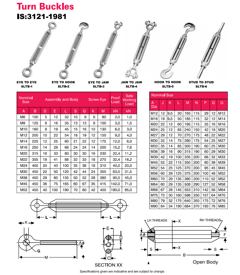
Commercially available turnbuckle in india as per Indian Standard IS 3121:1981
Links to other Topics in Machine design I
Machine Design I - Introduction to Design : Theory Q&A
Machine Design -I -Design of joints : Theory Q&A
Knuckle Joint : Design Procedure,Problems and Questions
Design of Levers : Hand Lever, Foot Lever, Bell crank lever
Design Of Bolted and Welded Joints
Design of Shafts: Theory and Numerical Problems
Couplings : Design Procedure and Numerical problems
Design Of SPRINGS : Questions and Numerical problems
Power Screw Design
Belt drives:Theory Q&A and Selection of Flat and V belts
- Log in to post comments