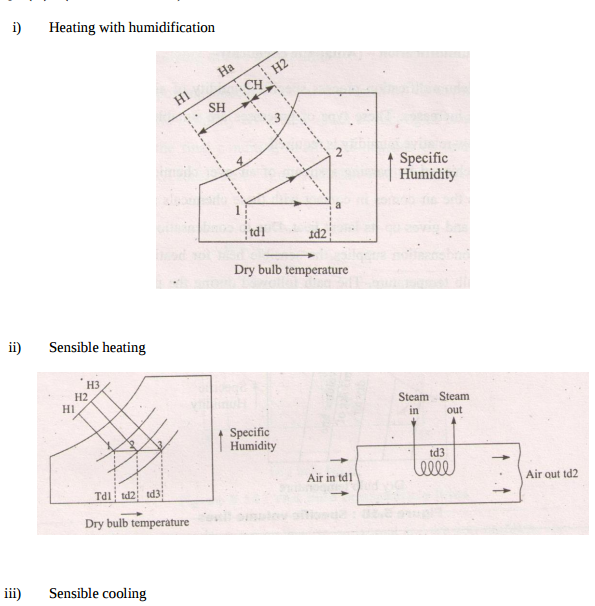
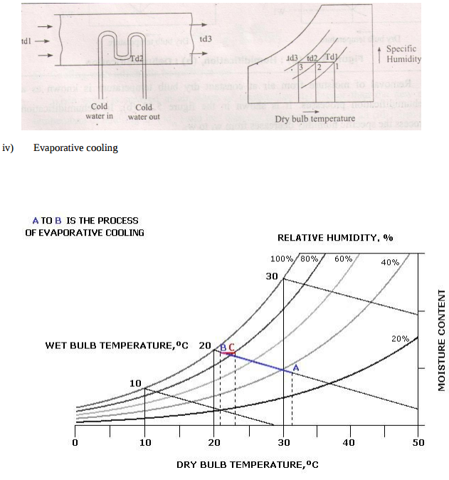
Represent following processes on Psychrometric chart............
Speed control of any actuator (Cylinders or motors) can be controlled using flow control valves. Varying the rate of flow of oil will vary the speed of the actuator.(Explanation 1Mark) In meter in circuit, rate of flow of oil is controlled at inlet of the actuator. In meter out circuit, rate of flow of oil is controlled at outlet of the actuator. In bleed off circuit, rate of flow of oil is controlled in the by-pass line leading towards the tank.
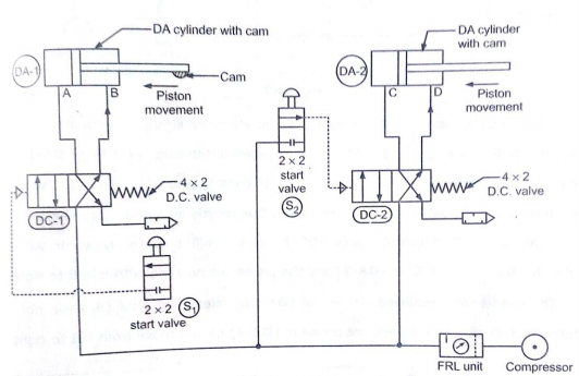
Explain with neat sketch (position based ) working of sequencing circuit for two double acting Air cylinders. Pneumatic double acting cylinders can be operated sequentially using a sequence valve or by using position based method. In pneumatics, use of sequence valve is not popular. Position based sequencing is possible using roller operated DCV or solenoid operated DCV. Various components required for Position based sequencing using roller operated DCV are as follows. I. Double acting cylinder - 02 Nos. II. 3/2 roller operated DCV – 02 Nos. III. 4/2 or 5/2 DCV – 01 No. IV.
.Draw and Explain pneumatic meter in circuit to control of speed extension. In meter in pneumatic circuit flow control valve with check valve is fitted between DCV and actuator. For speed control of actuator during extension stroke, FCV with check valve is fitted on piston side of the actuator as shown in figure. With a meter-in circuit, fluid enters into the actuator at a controlled rate. Pneumatic circuit diagram for meter-in flow-control circuit is as shown in figure. In this circuits, the rate of flow of compressed air into the cylinder is controlled by flow control
List the Factors to be considered for selecting the pipe while designing pneumatic system. Give specification of pipes for the pneumatic system. Factors to be considered while selecting the pipe for pneumatic system 1. Pressure of compressed air in the line. 2. Total flow rate per unit time through the line. 3. Permissible pressure drop in the line. 4. Type of tube material and type of line fittings. 5. Length and diameter of tube or other pipelines. 6. Working environment. Pipe Size Specifications: Generally pipe size is specified in three ways 1.
Varying the rate of flow of oil will vary the speed of the actuator. Speed control is possible using meter in circuit, meter out circuit, bleed off circuit or by placing flow control before the DCV. Speed control of bi-directional air motor: Bi-directional air motor rotates in clockwise as well as anti-clockwise direction. The speed of bi-directional motor is controlled as shown in fig. The speed control of motor by using variable two flow control valves having built-in check valve and 4x3 DC valve having zero position or central hold position with Pilot S1 and S2.
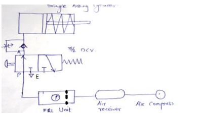
Figure 1 shows a symbol circuit of an impulse-valve controlled double acting pneumatic cylinder (A). The position of the impulse-valve (3), which is controlled by the start/stop-valve (1) and the end position valve (2), determines if the cylinder piston shall make a positive stroke and negative stroke. Positive piston stroke is initiated by manual activation of the start valve (1). Negative piston stroking takes place when valve (2) is activated by the cylinder rod at the position a1.
Answer: a pneumatic circuit for operation of two DA cylinders such that one operates after other using travel dependant sequencing as shown in fig.