You are here

4

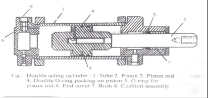
What are actuators ? Draw a double acting cylinder.

Actuator - Actuators are those components of hydraulic / pneumatic system, which produces mechanical work output. They develop force and displacement, which is required to perform any specific task. An actuator is used to convert the energy of the fluid back into mechanical power.


Name any four components of pneumatic system......................

1) Compressor: a)Pressure Requirement b) Volume of Air c) Compressor configuration 2) Actuators: a) According to maximum pressure b) According to application – Linear/Rotary c) shape and size of actuator 3) Air Receiver: a) Storage capacity b) Material of the tank 4) FRL unit: a) According to working environment b) According to pressure required at hand tools 5) DCV: a) According to maximum pressure of system. b) According to actuator configuration c) According to application- One hand /Two hand d) According to actuation method suitable for application

Explain any four criteria for selection of hydraulic pump in hydraulic system.

1) Pressure: It is the basic selection criteria. Pump pressurizes the hydraulic oil to the level required by actuator. When pressures up to 150 bars are required then gear pumps can be selected. For pressure of 150 to 250 vane pump is suitable and for above 500 bar pressure piston pumps are useful. 2) Flow of pressurized oil: Volumetric output of pump is measures in LPM. The flow of oil decides the speed of actuator. The displacement can also be changed for variable displacement pumps. 3) Speed of pump: The speed of pump is decided by rated capacity of the manufacturer.

Explain gear pump with neat sketch.........

It consists of one external and one internal meshing gear pair. External gear is connected to electric motor and hence is driving gear. Internal gear or ring gear is driven gear which rotates in same direction as that of external gear. Between two gear a spacer called ‘crescent’ is located which is a stationary pieces connected to housing. Inlet and outlet ports are located in end plates. External gear (driving gear) drives the internal gear (Ring Gear).

Explain 4-way-3 position direction control valve used in hydraulic system..........

4-way-3 position direction control valve used in hydraulic system is known as 4X3 DC Valve. The valve has four ports and three positions. Following figure shows the Normal and working positions of DCV. Spool of this valve is having three positions. The spool is so selected because we have to obtain third position also called as ‘Closed Centre Position’ This position is shown in figure. We have shifted the spool in such a manner that all ports are closed to each other. Mo flow from port P to port A or B and no flow from port A and B to R.

What is an accumulator ? Why accumulator is necessary for huge hydraulic pressers ?

makes available to the system whenever required. Necessity of accumulator for every huge hydraulic press: Oil requirement of the system is not continuous but intermittent. A hydraulic press needs the oil only during the lifting operation. While, during the lowering of load, holding the load or during idle period, it doesn’t not require any supply of oil. During such period, the hydraulic pump has to stop or delivered oil must be drained back to the sump. But frequent starting and stopping of pump is not desirable as it reduces the pump life.

Explain piston pump with neat sketch.............

It’s an inclined plate in axial piston pump on which all pistons are connected through piston rod. This swash plate is usually inclined. Use – It is helps to reciprocate the piston of axial piston pump while the cylinder block is rotating Working: Motor drives the shaft, which in turn rotates the entire cylinder block. The pistons are connected to inclined swash plate through piston rod. Now since swash plate is inclined and block is rotating, the piston reciprocates inside the barrel.

Draw and explain working of pressure reducing valve.........

Draw and explain working of pressure reducing valve. The main function of pressure reducing valve is to reduce the pressure in particular branch of the circuit to different level as demanded by consumer in that branch. Construction: It consists of spool and spring housed in the bore of valve body. Spring compression can be adjusted by pressure setting screw. Port P is pressure port connected to pump. Port A is consumer port requiring reduced pressure.


Pages

Subscribe to RSS - 4