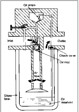
Draw labelled sketch of air lubricator..............
1) Compressor: a)Pressure Requirement b) Volume of Air c) Compressor configuration 2) Actuators: a) According to maximum pressure b) According to application – Linear/Rotary c) shape and size of actuator 3) Air Receiver: a) Storage capacity b) Material of the tank 4) FRL unit: a) According to working environment b) According to pressure required at hand tools 5) DCV: a) According to maximum pressure of system. b) According to actuator configuration c) According to application- One hand /Two hand d) According to actuation method suitable for application
1) Pressure: It is the basic selection criteria. Pump pressurizes the hydraulic oil to the level required by actuator. When pressures up to 150 bars are required then gear pumps can be selected. For pressure of 150 to 250 vane pump is suitable and for above 500 bar pressure piston pumps are useful. 2) Flow of pressurized oil: Volumetric output of pump is measures in LPM. The flow of oil decides the speed of actuator. The displacement can also be changed for variable displacement pumps. 3) Speed of pump: The speed of pump is decided by rated capacity of the manufacturer.
It consists of one external and one internal meshing gear pair. External gear is connected to electric motor and hence is driving gear. Internal gear or ring gear is driven gear which rotates in same direction as that of external gear. Between two gear a spacer called ‘crescent’ is located which is a stationary pieces connected to housing. Inlet and outlet ports are located in end plates. External gear (driving gear) drives the internal gear (Ring Gear).
4-way-3 position direction control valve used in hydraulic system is known as 4X3 DC Valve. The valve has four ports and three positions. Following figure shows the Normal and working positions of DCV. Spool of this valve is having three positions. The spool is so selected because we have to obtain third position also called as ‘Closed Centre Position’ This position is shown in figure. We have shifted the spool in such a manner that all ports are closed to each other. Mo flow from port P to port A or B and no flow from port A and B to R.
What is function of filters? Classify the filters and draw any two types of filters. Function of filter: To remove foreign particles from the oil and remove submicron particles dissolved in the oil. Classification of filters: 1- Full flow filter 2- Proportional flow filter Full flow filter: Incurs a large pressure drop. A relief valve is needed which cracks when the filter becomes blocked. Proportional flow filter: Localised low pressure area is formed at the venturi. The fluid is drawn from the filter due to the pressure difference. low pressure drop
1) Adaptor – To connect two pipes of different diameters. 2) Coupling- To connect two pipes of same diameters. 3) Tee- To connect two pipes with one pipe. 4) Cross- To connect two pipes in crosswise. 5) Elbow- To divert the flow between two pipes at right angle. 6) Hex nipple- To connect two pipes internally with the help of hexagonal nut. 7) 450 Elbow- To divert the flow between two pipes at 450 angle. 8) Reducer- To connect two pipes of different diameters and it will increase or reduce the pressure of flow
In any hydraulic circuit there are slight variations in presence of oil. When pressure changes the rate of flow changes but many circuits requires constant flow regardless of input or output pressure variations in the circuit then the pressure compensated FCV is used. It consists of hollow cylinder shaped poppet at the bottom of which there is a fixed orifice. There is a spring inside a poppet as shown in fig.