Q.1. State the functions to be performed by oil reservoir in a hydraulic circuit?
Ans : Following are the functions performed by the oil reservoir,
1) Storage of Hydraulic oil volume
2) Removal of Heat
3) Removal of Trapped air
4) Settlement of Contaminants
Q.2. Explain with sketch Hydraulic reservoir?
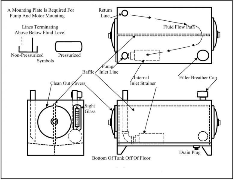
A hydraulic reservoir consist of following components,
1) Suction line and Return line : These two lines should be located as far away from ech other as possible, in order to guarantee that the oil volume is circulated effectively. Both lines should be sufficiently above the bottom to prevent sludge from stirring and getting inside the suction line.
2) Baffle plate : Suction and return lines are separated by the baffle plate. This is set up near the tank floor, and reaches closer to oil surface. This causes the flow of oil withn the tank and leads the return oil along the walls of the tank in order to improve cooling of oil.
3)Filter spout and air breather : The oil tank is filled through a filling strainer. This is a fine mesh through which the oil is filled in the tank. In order to maintain atmospheric air pressure inside the tank, and air breather must be provided for the pressure compensation. Air breather is mostly
combined with the filler spout.
4) Oil level indicator: Its function is to display the level of oil inside the tank.
5) Inspection covers and cleaning openings : Inspection covers, mostly fitted with the glass are provided in the side of the tank. From openings, it must be possible
to reach all points in the tank for interior cleaning purpose.
6) Oil drain tap(plug) ; the bottom of the tank is sloped, to move the deposit of sediment(sludge and water) at the lowest point in the tank. From where it can be drained off by means of a drain tap.
7) Tank covers : The design of tank covers depends upon what is to be mounted on it. If the pump is mounted on it its design is different. The pump can be mounted
vertically or horizontally on it.
Q.3. Explain with sketch Hydraulic oil filter?
Many fluid power systems fail simply because there is too much contamination in the medium. In fact, some estimate that 75% of all fluid power failures can be attributed to contamination issues.
This is why no fluid power system can be complete without the use of a filter. Hydraulic filters keep the hydraulic fluid contaminant free.
Figure below shows the commonly used filter, the bottom shell is removable for replacement of the filtering element. Such unit is installed in the return or suction line. The oil enters from the right side and then passes through the filtering paper cartridge(replaceable) then passes to the right side. While passing the oil leaves the contaminant inside the filter cartridge.
Q.4. What is the purpose of hydraulic oil seal? Explain any one type of oil seal.
Ans :Purpose of oil Seal
1) To stop leakage of oil
2) To maintain the pressure
3) To keep out contamination in the system
4) To enhance the working life of the system
5) To enhance the functional reliability of components over a longer period
‘O’ Ring Seal:
Figure shows ‘O’ ring seal. These are most common and simple seal with circular crosssection like ‘O’. Hence called O-ring is used as static as well as dynamic seal. The material used for O-Ring is synthetic rubber and is specified by its ID/OD. The round cross-section are non-positive seals. O-rings are fitted with back
ring the following figure depicts sealing of cylinder and piston by using ‘O’-ring with backup ring.
Q.5.What are the Factors to be considered for selection of seal and causes of its failure
Ans: Factors to be considered for
selection of seal
1. Shaft Speed The maximum allowable shaft speed is a function of the shaft finish, runout, housing bore and shaft concentricity, type of fluid being sealed and the type of oil seal material.
2. Temperature The temperature range of the mechanism in which the seal is installed must not exceed the temperature range of the seal elastomer.
3. Pressure Most conventional oil seals are designed only to withstand very low-pressure applications (about 8 psi or less). If additional internal pressure is present or anticipated, pressure relief is necessary.
4. Shaft Hardness Longer seal life can be expected with shafts having a Rockwell (RC) hardness of 30 or more. When exposed to abrasive contamination, the hardness should be increased to RC 60.
5. Shaft Surface Finish Most effective sealing is obtained with optimum shaft surface finishes. The sealing efficiency is affected by the direction of the finish tool marks and the spiral lead. Best sealing results are obtained with polished or ground shafts with concentric (no spiral lead) finish marks. If you must use shafts with spiral finish leads, they should lead toward the fluid when the shaft rotates.Q.21. Explain with sketch Pneumatic hose layers and state function of each layer?
6. Concentricity When the bore and shaft centers are misaligned, seal life will be shortened because the wear will be concentrated on one side of the sealing lip.
7. Shaft and Bore Tolerances The best seal performance is achieved when close shaft and bore tolerances are present. Other factors include shaft eccentricity, end play and vibration.
8. Runout Runout must be kept to a minimum. Movement of the center of rotation is usually caused by bearing wobble or shaft whip. When coupled with misalignment, this
problem is compounded. Contrary to popular belief and common practice, the installation of flexible couplings cannot correct or compensate for misalignment.
9. Lubricant Seals perform much better and longer when they are continuously lubricated with oil that has the correct viscosity for the application and that is compatible with the seal lip elastomer material. The consideration of seal incompatibility, particularly with certain additives and some synthetic lubricants, should not be ignored.
Causes of failure
1. Improper installation is a major cause
of hydraulic seal failure. The important things to watch during sealinstallation are:
(a) cleanliness,
(b) protecting the seal from nicks and cuts, and
(c) proper lubrication
2. Hydraulic system contamination is a another major factor in hydraulic seal failure 3. Chemical breakdown of the seal material .
4. heat degradation problems may involve reducing sea life.
Q.6.State any four reasons of failure of pneumatic seals.
Ans –
1. Incompatibility of seal material with operating system
2. Excessive heat
3. Excessive load
4. Excessive clearance
5. Excessive pressure
6. Improper fitting
7. Improper groove geometry
8. Abrasion
9. Wear
Q.7. State the function of accumulator?What are the different types of accumulators? Explain any one type of accumulator?
Ans :
Function of Accumulator: It is a pressure
vessel used in hydraulic system for following function
1. Primary function is to store hydraulic energy of pressurized oil during idle period and make available again when it is required by the system.
2. To meet peak demands of hydraulic energy, smooth out pressure shocks/surges .
Different types of accumulator:
According to element used for store oil under pressure types of accumulator are:
1. Dead weight type accumulator: The dead weights may be of some heavy materials like iron or concrete blocks are placed on the piston platform.
2. Spring loaded Accumulator: The compression spring with high stiffness is used to exert force on the piston to store hydraulic energy of oil.
3. Gas charged Accumulator: The gas bladder is charged with dry nitrogen gas and force is created with the help of gas pressure inside the bladder.
Dead Weight type accumulators
Working;
1. It consists of piston loaded with dead weight and moving within a cylinder which exerts pressure on the oil.
2. The oil will enter from the inlet provided at the bottom and pushes the piston in upward direction against the load exerted by the dead weight placed on the platform.
3. When piston moves to the upper end the accumulator get charged and it can be used whenever oil energy is needed.
Q.8.Explain with sketch Working of bag type accumulator
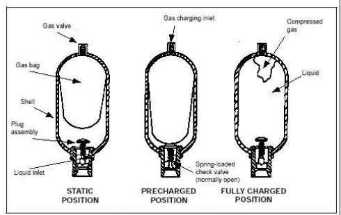
This accumulator consists of a seamless high-pressure shell, cylindrical in shape, with domed ends and a synthetic rubber bag that separates the liquid and gas (usually nitrogen) within the accumulator. The bag is fully enclosed in the upper end of a shell. The gas system contains a high-pressure gas valve. The bottom end of the shell is sealed with a special plug assembly containing a liquid port and a safety feature that makes it impossible to disassemble the accumulator with pressure in the
system. The bag is larger at the top and tapers to a smaller diameter at the bottom. As the pump forces liquid into the accumulator shell, the liquid presses against the bag, reduces its volume, and increases the pressure, which is then available to do work.
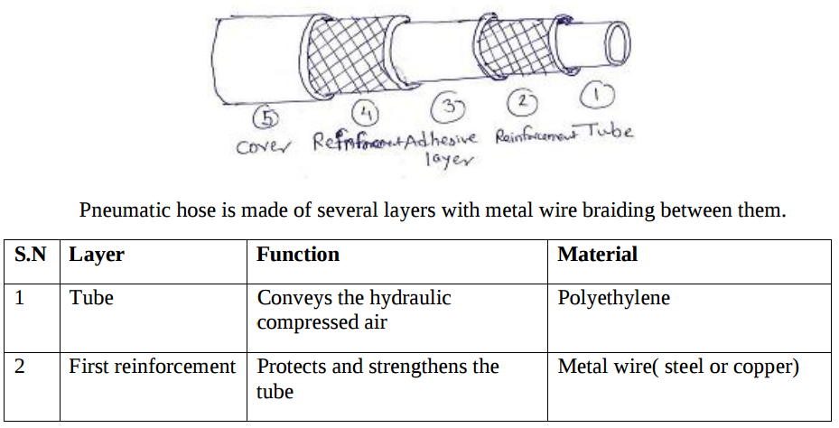
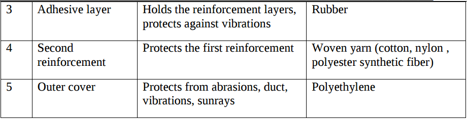
Q.9. Explain with sketch Pneumatic hose layers and state function of each layer?
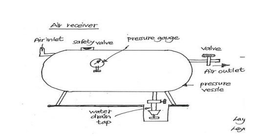
Q.10. Explain with sketch air receiver?
Q.11. Explain with sketch Muffler used in pneumatic system?
Muffler is a device which is used in the pneumatic system to reduce the noise created by exhausting air. It does exactly what a silencer does in an automobile.Mufflers are attached to the exhaust port of air valves, cylinders or motors. Several designs have been developed, some of them patented by various manufacturers but with the central core of dissipating the exhaust energy.
Figure above shows a common type of muffler in which the air is passes through series of baffles, which are perforated metal tubes. Which are fitted one in another. As the air stream enters from left end and passes throught the series of baffles the air looses its velocity and hence the noise is lost while
exhausting.
- Log in to post comments