Q.1. Explain with sketch 'Air Filter'.
Ans : An ideal air filter would be one, which would remove all foreign materials and allow dry, clean air to flow without restriction. The primary function of filter is to remove dirt and smoke particles in air. It also performs secondary function of condensing and removing water vapor that is present in the air
passing through it. Filters are classified according to the method of removal of dirt particles (as mechanical type, electricallypolymerized type), mesh size of filtering element (as fine, coarse and micro-filters) and filtering material (as synthetic type, impregnated felt type etc.)
Q.2. Explain with sketch Dual pressure valve used in Pneumatics.
The choice of type of filters depends upon the quality of air required, the normal air conditions, and accessibility to filter for repair or replacement of filtering element. Figure 19.1 shows a typical filter (mechanical type and using impregnated felt as the filter element).The filter has an inlet port from which
moist and dirty air enters, the air then passes through the filtering element and while passing, the dirt particles remain in the outer mesh. As well due to pressure drop the moisture contained in air gets condensed and drops in the glass tube below. A liquid condensate removal tap is provided at bottom of glass tube for liquid
condensate removal. The filters are rated by the mesh size as well the capacity of air flow.
Q.3. Explain with sketch Pressure Regulator.
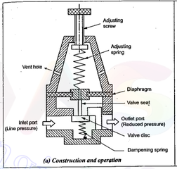
Ans: A pressure regulator also called pressure-reducing valve is necessary to maintain the pressure at adesired level. The regulator also acts as a pressure guard by
preventing pressure surges or drops from entering the air circuit. The regulators are diaphragm type or the piston type.
Construction:
Q.4. Explain with sketch Dual pressure valve used in Pneumatics.
he diaphragm type pressure reducing valve consists of a diaphragm, made up of synthetic rubber, allows the proper movement for opening and closing of valve, without mechanical friction. The topside of diaphragm is in contact with lower spring rest where as the bottom side of diaphragm is contact with valve pin. This pin moves the valve from its seat.With the adjusting screw in fully retracted position, the valve is closed. As the adjusting screw is turned to compress the regulating spring, the valve is opened. The pressure at which air leaves the valve depends upon the size of valve opening. The valve acts automatically to maintain relatively constant outlet pressure. Thus if air pressure on discharge side of valve increases momentarily, it acts against the diaphragm to decreases the pressure exerted by the regulating spring on the valve. The valve moves upward, towards the closing position, greater throttling action takes place, and the pressure is reduced. Thus, the valve performs regulatory action.
Q.5. Explain with sketch Lubricator used in Pneumatic system.
Ans: In pneumatic systems since the working medium is air, additional means of lubrication are required to keep friction and wear to a minimum. It has been observed that two identical air cylinders, one with absolutely no lubricant and other with proper lubricant, showed a great difference in their seal life,
and lack of proper lubrication leads to rusting and pitting in the tubes due to air moisture.
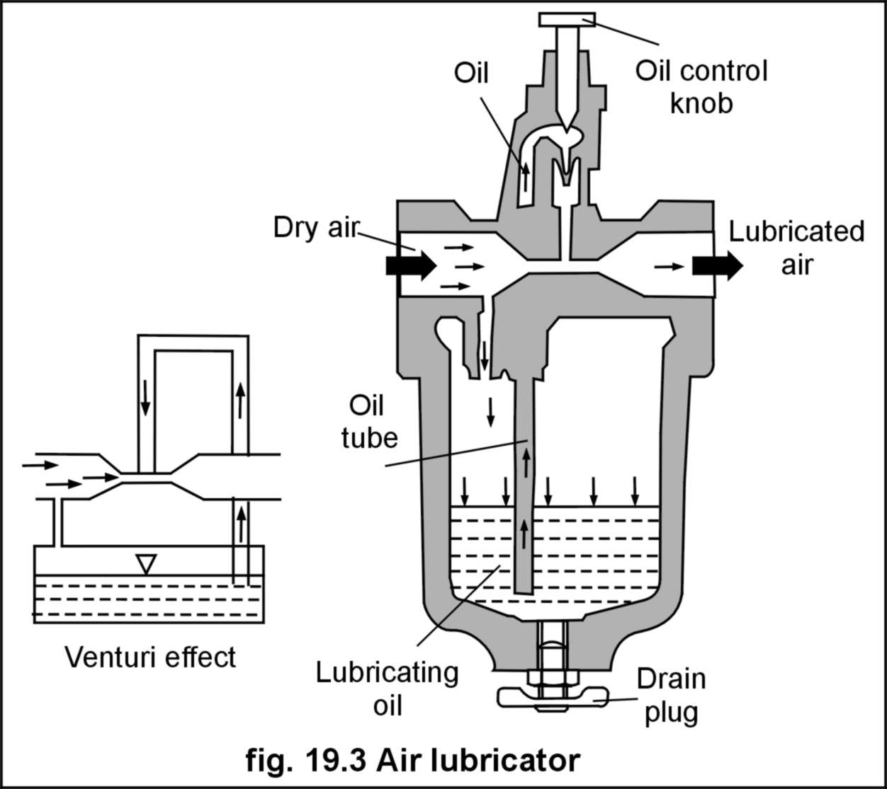
There are number of types and designs of lubricator available from different manufactures.The figure above shows a common design in which venturi effect (as that of used in automotive carburetor) is
used to mix oil into air. Due to the pressure difference between oil surface and venturi throttle, the oil is forced up into the tube and it is carried away by air. The lubricator similar to a filter has a
sight feed glass, which shows quantity of oil present in the flask. Metering of oil is accomplished by a needle valve, which provides variable sized orifice. The lubricator can be filled manually shutting off the air pressure. The oil is atomized by air in the venturi tube.
Q.8. Explain with sketch the function of each element in FRL unit used in pneumatics. Also show its symbol.
Ans:
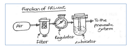
It is service unit used in Pneumatic system which is combination of three devices named as Filter, Regulator and Lubricator. Function of FRL Unit: 1. Filter: It
is used for separate out or filter out contaminants present in the compressed air.
2. Regulator: It is pressure control device used for regulating pressure of compressed air to the desired pressure at a steady state condition.
3. Lubricator: It is a device which is used for addition of lubricating oil particles in compressed air for lubrication of sliding or moving pneumatic components.
Sketch of the combined unit
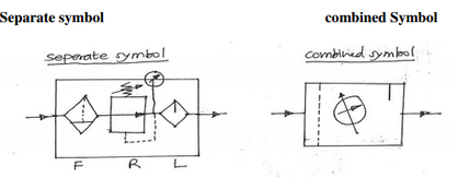
Symbol of the FRL unit together and separates
Q.6. Explain with sketch the Quick Exhaust valve used in Pneumatics
Ans:
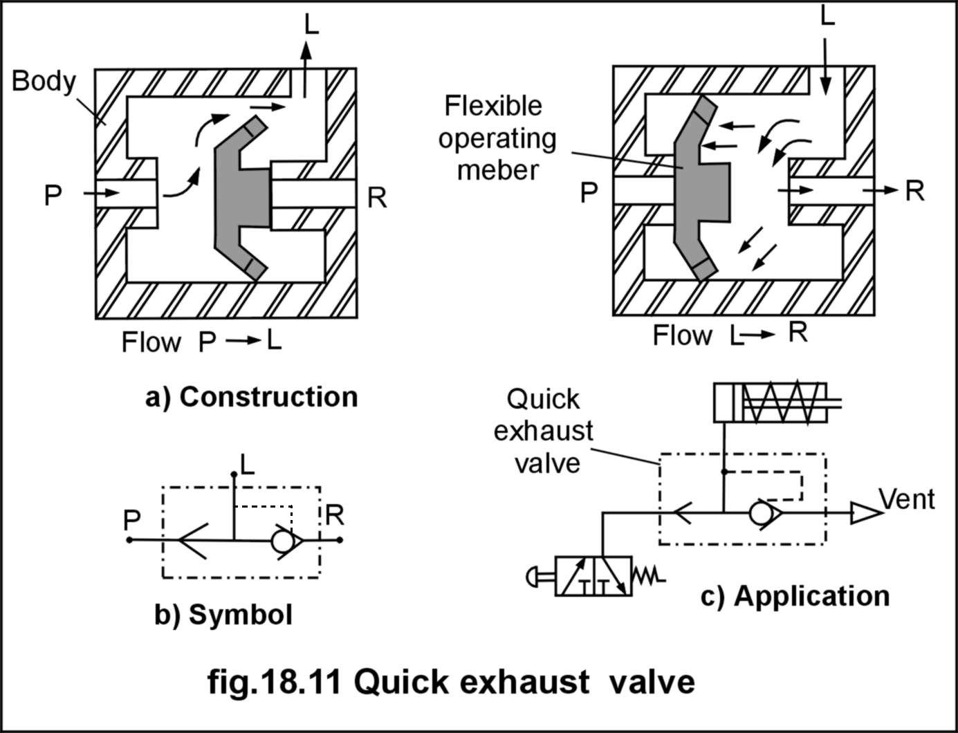
A quick exhaust valve, as the name implies is used for quick exhaust of the air from the actuator. In normal system (without quick exhaust valve), the air has to return through piping and valves. But since air is to be ultimately drained to atmosphere (and not to be returned to reservoir as in hydraulic system), it is efficient to drain it (called venting) directly to atmosphere as it leaves the actuator, this reduces the back pressure as well saves energy, required for driving out the air. This speedups the return stroke also.
Construction of a quick exhaust valve is shown in figure below. Similar to shuttle valve it has three ports namely pressure (P), load (L) and vent (R). It has an operating member (generally a movable disc). In normal forward stroke the disc moves to right opening port “P” to load “L”, as well closing
the vent ‘R’. In return stroke, the returning air pushes the flexible disc to left, closing the port “P” and at the same time
opening the vent “R”. Thus the air from load (L) is directly vented to atmosphere
Q.7. Explain with sketch the Shuttle valve used in Pneumatics
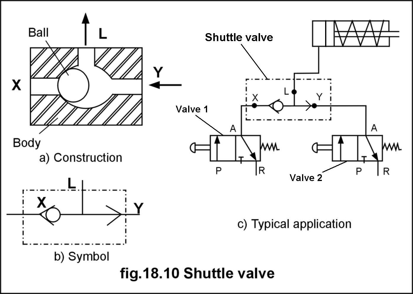
A shuttle valve also called as double check valve, which allows pressure in a line to be obtained fromalternative sources Construction, symbol and application of
a ball type shuttle valve is depicted in figure below . It consists of an operating element (which may ball or cone), which is free to move in a body, depending upon the side from which pressure is obtained. It has three ports namely X,Y and L.
The port “L” is output (load) port. The air is supplied to port “L”, by the valve either from “X.” or “Y”, from whichever pressure is applied, but at the same time,
the valve closes the flow “X” to “Y” or viseversa. An application of shuttle valve to operate single acting cylinder from two sources is also shown in
figure 18.10. When valve 1 is actuated, the compressed air is applied to the port “X”, the shuttle valve closes the port “Y” and supplies air to the cylinder through port “L”, and when valve 2 is actuated, the compressed air is applied to the port “Y”, the shuttle valve closes the port “X”, causing the cylinder to be fed
from port “L”.
Q.8. Explain with sketch the Time Delay valve used in Pneumatics.
Pneumatic time delay valve is used when time based sequencing is required. Construction and symbol of valve is shown in fig.18.12. It is simply a 3/2 direction control valve, which is impulse operated from one side. Time delaying is achieved by delaying the impulse actuation. The valve has an in-built air
reservoir and in-built non-return flow control valve.When impulse is applied to port “Z” for valve actuation, the air passes through needle control valve,
which controls the rate of flow, further the valve spool is not actuated until the air reservoir is filled completely and pressure isbuilt-up. (This time difference between impulse application at “Z” and actual spool actuation is the “delay”, which is adjustable
through needle valve). This valve is found applicable in time based sequencing, which is common industrial application, e.g. clamping, indexing, feed motions etc.


Q.9. Explain with sketch Dual pressure valve used in Pneumatics.
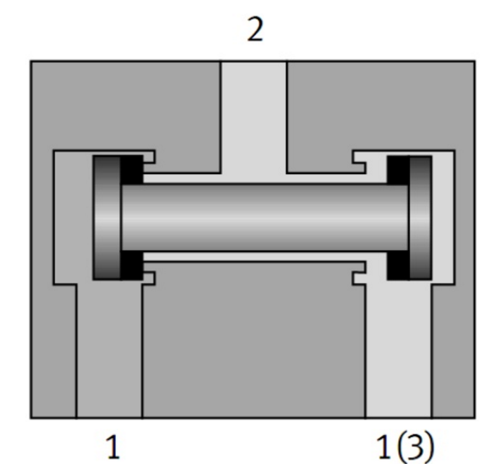
A two pressure valve requires two pressurised inputs to allow an output from itself. This is achieved by a similar system to the one shown below, one active input slides the shuttle valve shut blocking any air flow, add two active inputs and the shuttle remains centralised allowing flow through the valve
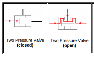
These valve types are commonly associated but not limited to safety circuits, for example a two push button operation system whereby an operator is required to use both hands to activate two push buttons, this would ensure the operators hands are out of reach of any hazardous operations.
- Log in to post comments

