Q.1. Explain with sketch hydraulic circuit for the Milling machine.
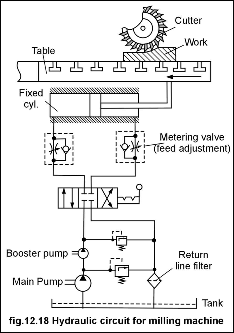
Ans: Hydraulic circuit for a milling machine is comparatively different from the former two circuits, because the table movement in millingoperation is comparatively slower. As well, different feeds (adjustable) are required for milling different type of work. Hence, in the hydraulic circuit for milling machine in addition to other
elements a flow control valve (graduated in terms of feeds) is incorporated in the circuit. Figure depicts the hydraulic circuit formilling machine. It has a main pump, which is a low pressure, and high discharge pump, and one booster pump, which is a low discharge high pressure pump. The function of the booster pump is to boost the
hydraulic pressure to a level above that of provided by main pump ( this combination saves the power as well as use of a high flow and high discharge pump is avoided).There are two sets of flow control valve and check valve, fitted in both supply and return line to cylinder, to achieve speed control in both directions. A manually operated spool valve decides the direction of flow to the cylinder

Q.2. Explain with sketch hydraulic circuit for the GRINDING machine.
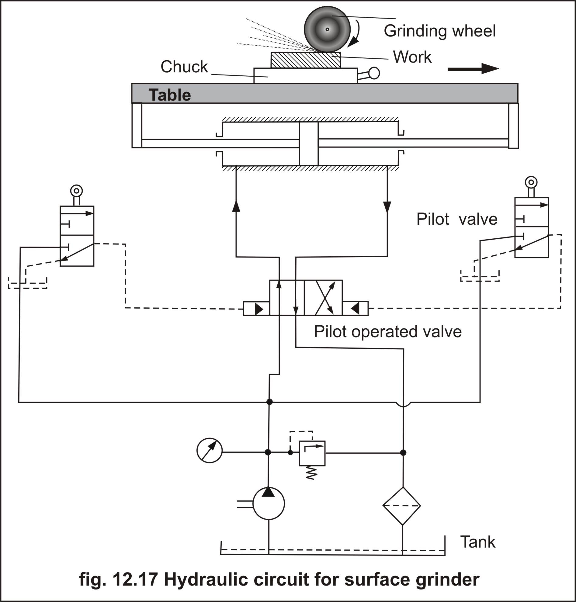
Ans : Hydraulic circuit for a surface grinding machine is depicted in sketch below. It consists of a power pack to supply pressurised oil, one pilot operated direction control valve which decides the direction of flow of pressurized oil.The piston rods on both sides are mechanically coupled with the table of the machine. There are two
roller actuated pilot valves, which are actuated by cams fitted to the table ( cams not shown in diagram). These valves provide pilot impulse to the main valve, thus deciding the position of main valve and hence the direction of motion of the cylinder ( and consequently the table). Every time either of the pilot valves is pressed by the cam. The cam positions are adjustable, which decides the strokelength movement of the table. Whenever the work-piece to be ground is changed the operator is required to change the position of the cams to suit the length of work-piece.

Q.3. Explain with sketch hydraulic circuit for the SHAPING machine.
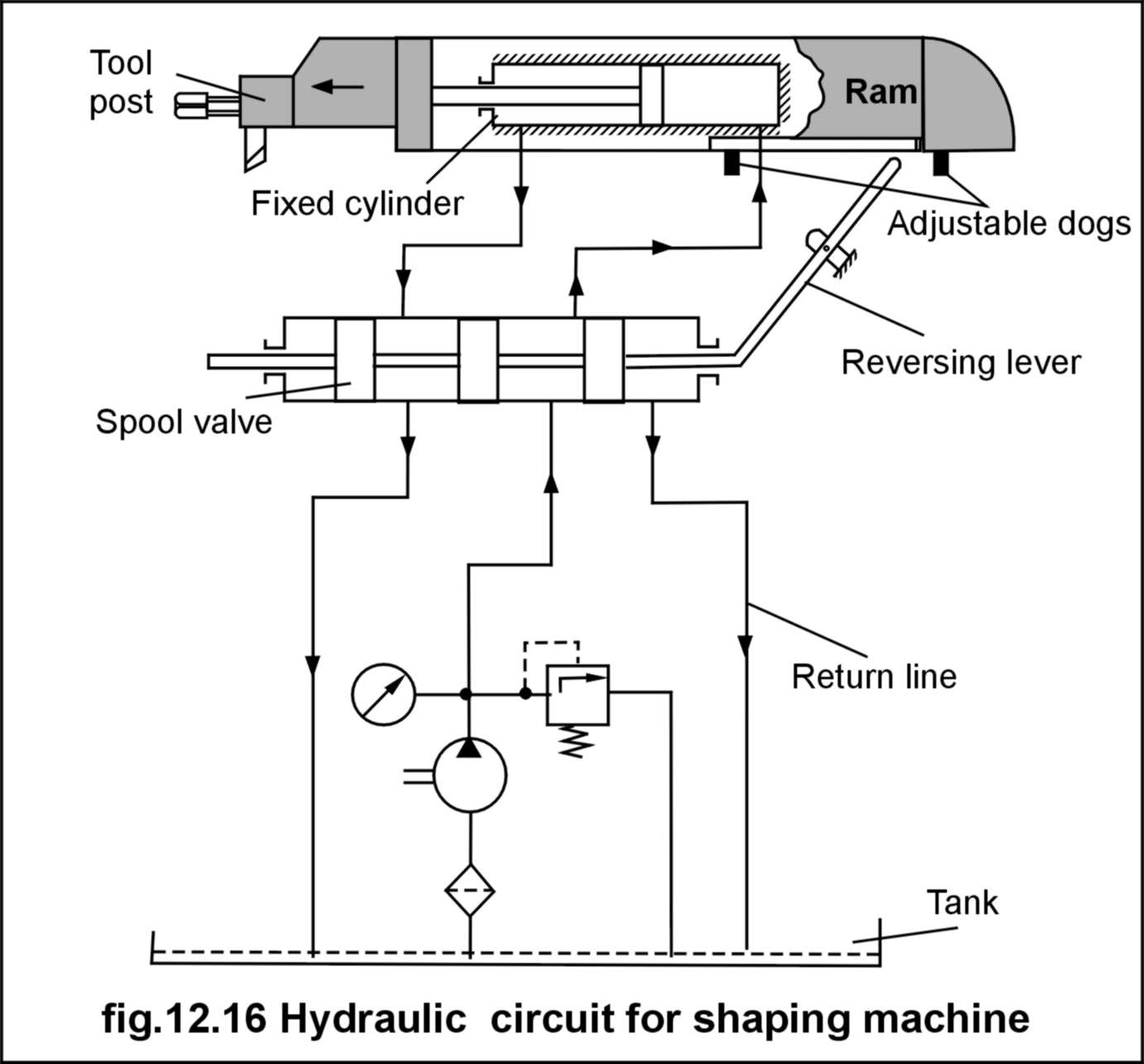
Ans : Figure below depicts the hydraulic circuit for shaping machine. The circuit utilizes a double acting cylinder with single piston rod and spool type directional control valve, which is shifted by a reversing lever.Hydraulic power-pack supplies the pressurised oil to the spool valve. The position of spool valve
decides whether the pressurised oil should go the head end or the piston rod end of the cylinder. The cylinder is mounted in such amanner that the forward stroke occurs when the oil is supplied to the head end of the cylinder and reverse stroke occurs when oil is supplied to piston rod end of the cylinder. Due to the difference in
annular areas of head end and piston rod end, the return stroke is faster than the forward stroke. The stroke length of the ram can beadjusted by changing the positions of the adjustable dogs, i.e. closer the adjustable dogs shorter the stroke length and vice-versa.Several additional controls may be added to this basic circuit to
enhance its performance and to have precise control over operation.

- Log in to post comments
