You are here

THEROY

Design of Levers : Hand Lever, Foot Lever, Bell crank lever

Submitted by sameerengr on Sat, 07/09/2022 - 16:13

Design of levers 

Key points to remember regarding design of levers :

  • the design of levers is all about finding the dimensions of the levers so that it could perform its function satisfactorily
  • A lever is force multiplier, depending upon the location of the load and effort from the fulcrum point.
  • Levers are classified on the basis of location of load, effort and fulcrum point.

Define (i) Dew point temp. (ii) Wet bulb temp

i) DPT – Dew point temperature tDP - It is the temperature at which air water vapour mixture starts to condense. D.P.T. of mixture is defined as the temperature at which water vapours starts to condense.

Ii) WBT - Wet bulb temperature - tWB - It is the temperature recorded by thermometer when its bulb is covered with wet cloth known as wick and is exposed to air.

Name four sensors used in I.C. engine and explain working of any one.

Sensor used in IC engines ( Explanation of any one )

A sensor is an input device that provides variable information on an engine function. Examples of sensors include the airflow sensor (AFS), crank angle sensor (CAS), throttle potentiometer sensor (TPS) etc, and these provide data on load, rpm, temperature, throttle opening etc. This data is signaled to the ECM, which then analyses the results and computes an output signal. The output signal is used to actuate an n output device.

What is jet propulsion ? Give the classification of jet propulsion system.

Jet Propulsion: This is done by expanding the gas which is at high temperature & pressure through the nozzle so that the gas with very high velocity leaves the nozzle giving thrust in opposite direction. - Principle is based on Newton’s Second & third law of motion. Jet propulsion – Classification (1) Atmospheric jet engines (breathing engine) -Turbojet engine - Turbo prop engines - Ram jet (2) Rocket engine (Non - breathing engine)

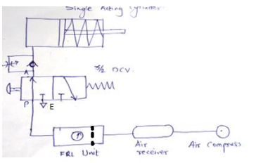
Explain with neat sketch (position based) working of sequencing circuit for two double acting Air cylinders.

Explain with neat sketch (position based ) working of sequencing circuit for two double acting Air cylinders. Pneumatic double acting cylinders can be operated sequentially using a sequence valve or by using position based method. In pneumatics, use of sequence valve is not popular. Position based sequencing is possible using roller operated DCV or solenoid operated DCV. Various components required for Position based sequencing using roller operated DCV are as follows. I. Double acting cylinder - 02 Nos. II. 3/2 roller operated DCV – 02 Nos. III. 4/2 or 5/2 DCV – 01 No. IV.

Draw and explain pneumatic meter in circuit to control of speed extension.

.Draw and Explain pneumatic meter in circuit to control of speed extension. In meter in pneumatic circuit flow control valve with check valve is fitted between DCV and actuator. For speed control of actuator during extension stroke, FCV with check valve is fitted on piston side of the actuator as shown in figure. With a meter-in circuit, fluid enters into the actuator at a controlled rate. Pneumatic circuit diagram for meter-in flow-control circuit is as shown in figure. In this circuits, the rate of flow of compressed air into the cylinder is controlled by flow control

Pages

Subscribe to RSS - THEROY