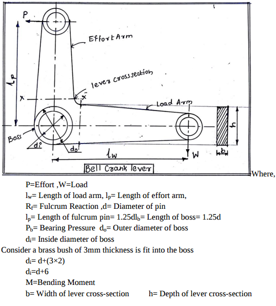
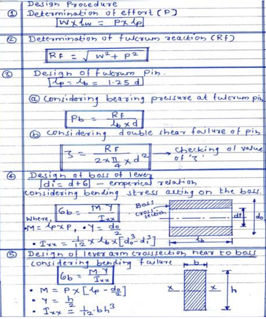
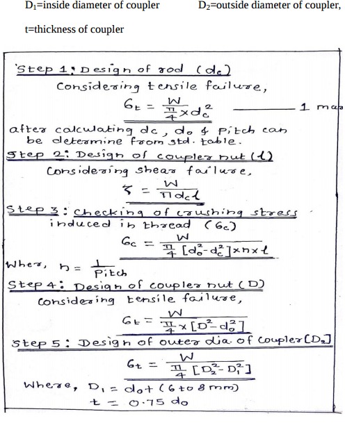
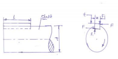
Draw a neat sketch of bell crank lever. Enlist steps in designing the bell crank lever
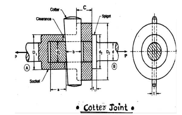
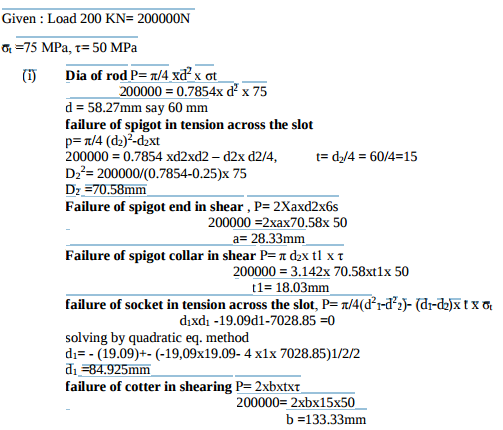
It consist of 3 elements i. Socket ii. Spigot iii. Cotter Where, d= End diameter of rodd1= Diameter of spigot/ID of socket d2= Diameter of spigot collar D1= Outer diameter of socket D2= Diameter of socket collar C=Thickness of socket collar t1= Thickness of spigot collar t= thickness of cotter b= Mean width of cotter a= Distance of end of slot to the end of spigot P= Axial tensile/compressive force σt, σc, τ= Permissible tensile, compressive, shear stress for the component material
a. When cotter is driven through the slots, it fit, fight due to wedge action. This ensures tightness of joint in operation and present loosening of the parts. b. Due to taper, it is easy to remove the cotter and dismantle the joint. The normal value of taper varies from 1 in 48 to 01 in 24 and it may increase to 1 in 8
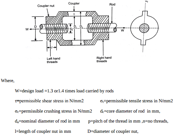
Write any four equation s in the design of turn buckle with relevant sketches
Design of Knuckle joint Failure of rod in tension
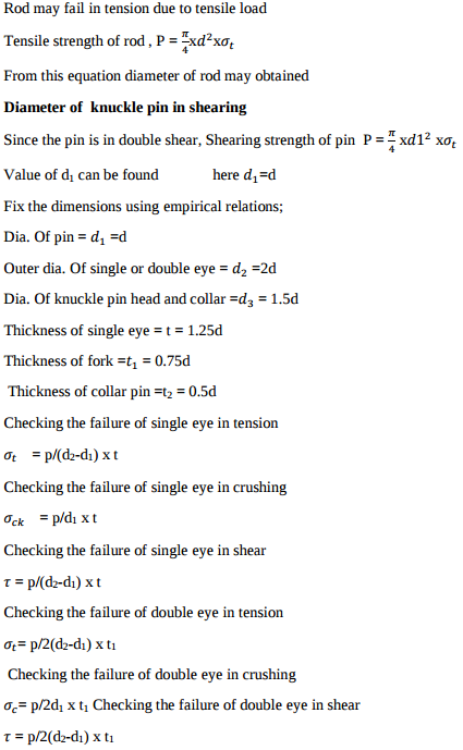
Applications of cotter joint: cotter foundation bolt, big end of the connecting rod of a steam engine, joining piston rod with cross head, joining two rods with a pipe Applications of knuckle joint: link of bicycle chain, tie bar of roof truss, link of suspension bridge, valve mechanism, fulcrum of lever, joint for rail shifting mechanism
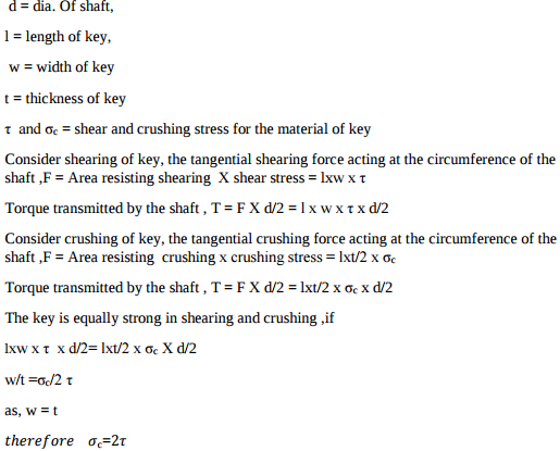
T= Torque transmitted by the shaft , F= tangential force acting at the circumference of the shaft,
In the first type of levers, the fulcrum is in between the load and effort. In this case, the effort arm is greater than load arm, therefore M.A. obtained is more than 1 Application: Bell crank levers used in railway signaling arrangement, rocker arm in I.C. Engines , handle of a hand pump, hand wheel of a punching press, beam of a balance, foot lever (any 1) In the second type of levers, the load is in between the fulcrum and effort. In this case, the effort arm is more than the load arm, therefore M.A. is more than 1.
Methods of reducing stress concentration in cylindrical members with holes . Stress concentration can be reduced in cylindrical members with holes by providing additional holes in vicinity of holes as shown in fig. (ii). Fig (i) Showing cylindrical member with hole at center having stress line in disturb manner at vicinity of hole and component will fail at hole so for fig (i) ,stress concentration is more . fig. (ii) members shoulder having additional hole in vicinity of hole and therefore stress line maintain spacing between them so here stress concentration is less.