Question and answers
| Que.No | Marks | |
|---|---|---|
| Q 2 f ) |
4 |
Question:A pulley rotating at 50 m/s transmits 40 kW. The safe pull in belt is 400 N/cm width of belt. The angle of lap is 170º. If coefficient of friction is 0.24, find required width of belt.Answer: Data: Initial tension, To = 2000 N, coefficient of friction, µ = 0.3, Angle of lap, θ = 1500 = 1500 x П / 180 = 2.618 rad, Smaller pulley radius, R = 200 mm, hence, D = 400 mm, Speed of smaller pulley, N = 500 r.p.m. We know that the velocity of the belt, v = П = П = 10.47 m/sec (01 mark) Let T1 = Tension in the belt on the tight side, N Let T2 = Tension in the belt on the slack side, N We know that, T0 = Hence, 2000 = (T1 + T2) / 2 Thus, (T1 + T2) = 4000 N ....................... (1) We also know that, = therefore, = or = 2.2 ............. (2) From equations 1 and 2, T1 = 2750 N and T2 = 1250 N (02 marks) Power transmitted by belt, P = [T1 - T2] v = [2750 - 1250] 10.47 = 15700 watts = 15.7 kW ----------------------------------------------------------------------------------------------------- |
| Q 2 f ) |
4 |
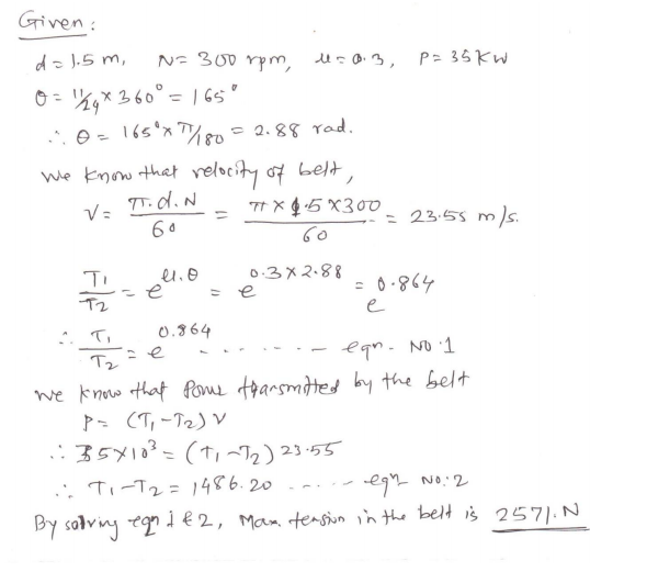
Question:A flat belt drive is required to transmit 35 kW from a pulley of 1.5 m effective diameter running at speed of 300 rpm. The angle of contact is spread over 11/24 of the circumference co-efficient of friction for the surface is 0.3. Determine the maximum tension in the belt.Answer:
|
| Q 3 ) |
8 |
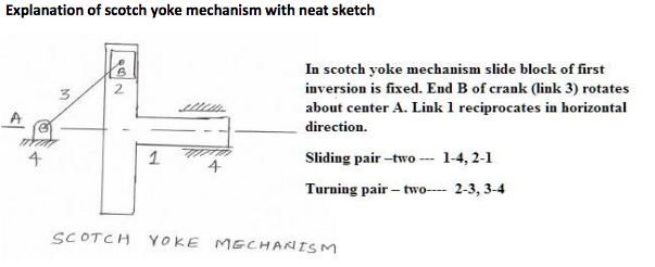
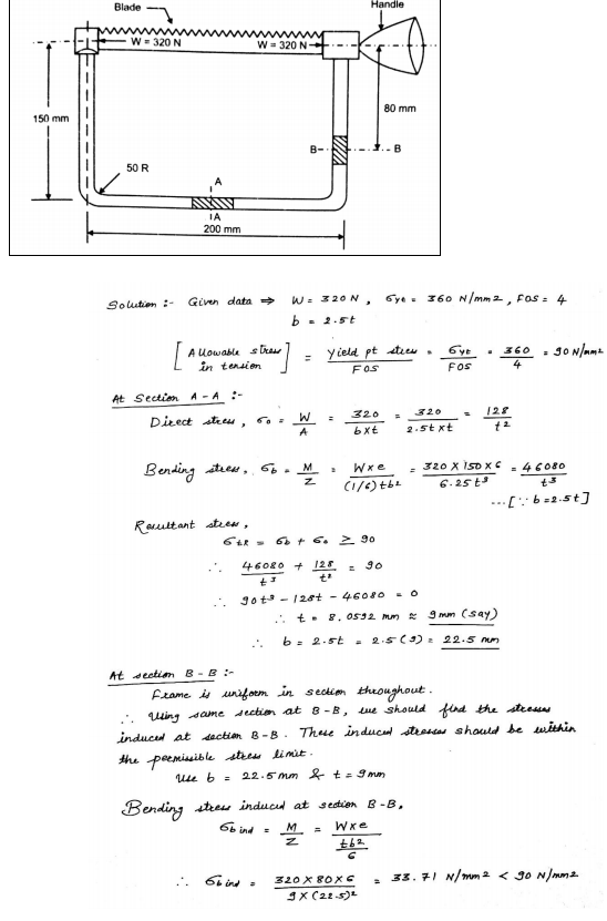
Question:Fig.1Show of hacksaw The belt is assembled with tensoionAnswer:
|
| Q 3 a ) |
4 |
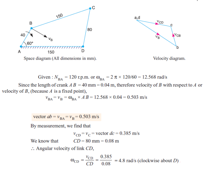
Question:In a four bar chain ABCD, AD is fixed and is 150 mm long. The crank AB is 40 mm long and rotates at 120 r.p.m. clockwise, while the link CD = 80 mm oscillates about D. BC and AB are of equal length. Find the angular velocity of link CD when angle BAD = 60.Answer:
|
| Q 3 a ) |
4 |
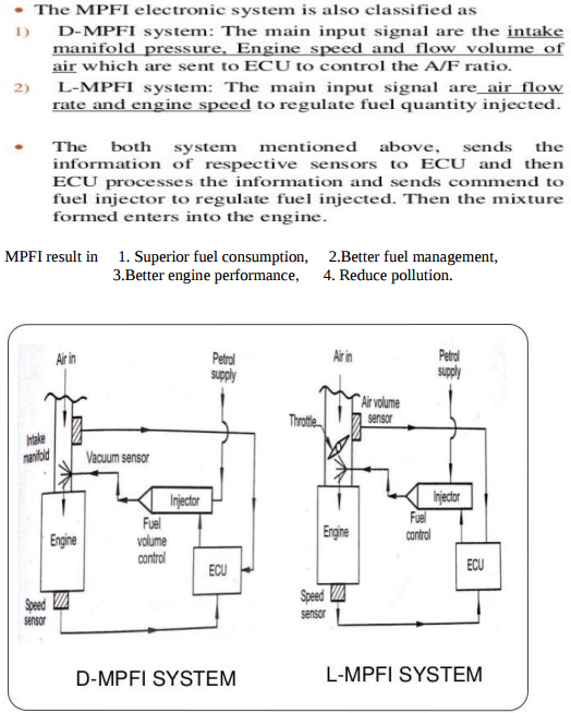
Question:Explain MPFI with neat sketch.Answer: Attempt any FOUR MPFI : MPFI means Multipoint Injection System in which each cylinder has number of injector to supply / spray the fuel in cylinders.
|
| Q 3 a ) |
4 |
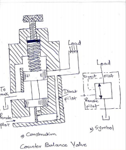
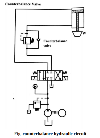
Question:Explain the working of counter balance valve in hydraulic circuit.Answer: Counter Balance Valve It is basically a relief valve but it is used to set up a back pressure in a circuit to prevent load from falling. They are frequently employed in vertical presses, loaders, lift trucks and other machines that must maintain a particular position or hold a suspended load. In such applications, the counterbalance valve creates a back pressure to prevent the movement of piston rod of cylinder Figure shows a typical counterbalance valve. At the present pressure (due to load) acting at port A, the valve remains closed under the spring force. The fluid in the port A is trapped thereby prevents the movement of the load. When the pressure in the port A increases beyond certain value, it acts on the spool from downward direction. The spool moves against the spring force and provides the passage for the fluid to tank. This allows descending of the load. As this valve gets actuated line pressure, it is known as direct operated counterbalance valve.
|
| Q 3a)(i) |
4 |
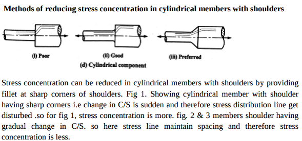
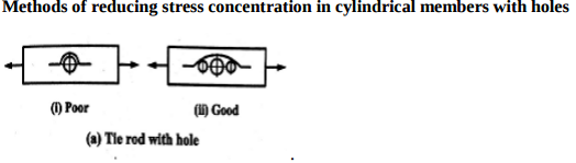
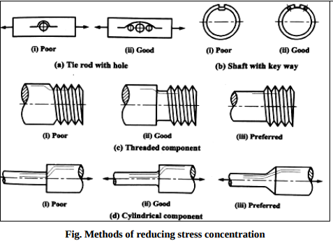
Question:Explain with neat sketches only (i) Methods of reducing stress concentration in cylindrical members with shoulders. (ii) Methods of reducing stress concentration in cylindrical members with holes.Answer:
----------------------------------------------------------------------------------------------------- |
| Q 3 b ) |
4 |
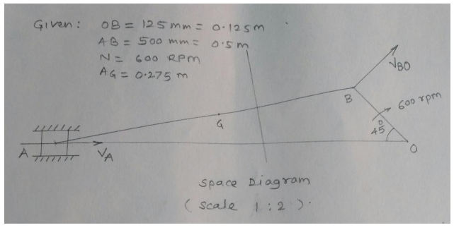
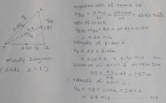
Question:In a slider crank mechanism, the length of crank OB and connecting rod AB are 125 mm and 500 mm respectively. The centre of gravity G of the connecting rod is 275 mm from the slider. The crank speed is 600 rpm clockwise. When the crank has turned 45 from the inner dead centre position, determine : (i) Velocity of slider ‘A’, (ii) Velocity of the point ‘G’ graphically.Answer:
|
| Q 3 b ) |
8 |
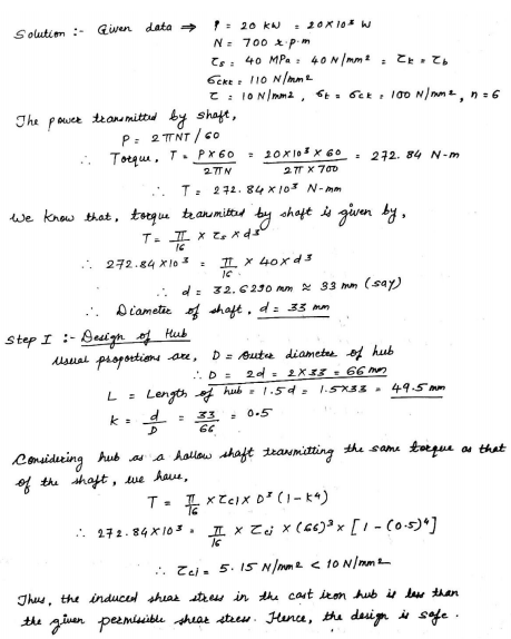
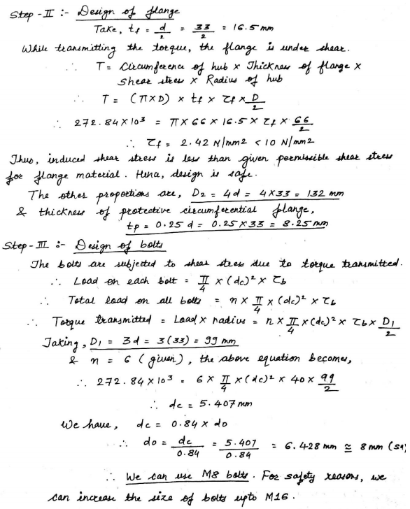
Question:In a rigid flaninged complended to transmit 20K.W at 700.r.p.mAnswer:
|
| Q 3 b ) |
4 |
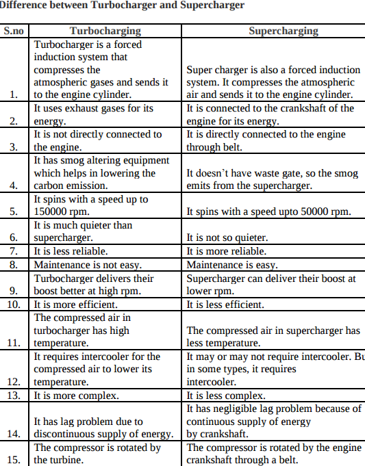
Question:Differentiate supercharging and turbocharging in I.C. engine.Answer:
|
| Q 3 b ) |
4 |
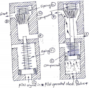
Question:Discuss pilot operated check valve with neat sketch.Answer: When pilot signal of pressurized oil is used to control movement of poppet in the check valve, it is called as pilot operated check valve. It is used when no flow characteristics of the valve is desired only for a portion of the system cycle. Figure shows the pilot operated check valve. A pilot piston is introduced below moving poppet. This pilot piston can move up by introducing pilot signal. Working: In normal position there is no flow from (A) to (B) because the movable valve poppet has blocked the flow. Now pilot signal is given through port (C). This oil will push up the pilot piston upwards, thereby compressing springs (S1). The piston rod of pilot piston will push the movable poppet in upward direction thereby compressing the spring (S2). Now the flow from (A) to (B) will start. As and when we cut-off the pilot signal the flow from (A) and (B) will continue. When pilot signal will be cut-off, spring S1 and S2 will expand and moving poppet will again block the flow from (A) to (B).
|
| Q 3 c ) |
4 |
Question:Explain slip and creep phenomenon in belts.Answer: Define slip and creep in the belt drive Slip --- Slip is defined as insufficient frictional grip between pulley (driver/driven) and belt. Slip is the difference between the linear velocities of pulley (driver/driven) and belt. Creep ----- Uneven extensions and contractions of the belt when it passes from tight side to slack side. There is relative motion between belt and pulley surface, this phenomenon is called creep of belt. ----------------------------------------------------------------------------------------------------- |
| Q 3 c ) |
8 |
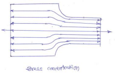
Question:Define stress concentration. What are the causes of stress concentration? State any four methods of reducing stress concentration with neat sketches.Answer: Stress concentration: Whenever a machine component changes the shape of its cross section, the simple stress distribution no longer holds good and the neighbourhood of the discontinuity is different. This irregularity in the stress distribution caused by abrupt changes of form is called ‘stress concentration’.
Causes of stress concentration The various causes of stress concentration are as follows: (i) Abrupt change of cross section (ii) Poor surface finish (iii) Localized loading (iv) Variation in the material properties Methods of reducing stress concentration The presence of stresses concentration cannot be totally eliminated but it can be reduced, so following are the remedial measures to control the effects of stress concentration. 1. Provide additional notches and holes in tension members. a) Use of multiple notches. b) Drilling additional holes. 2. Fillet radius, undercutting and notch for member in bending. 3. Reduction of stress concentration in threaded member. 4. Provide taper cross-section to the sharp corner of member
|
| Q 3 c ) |
4 |
Question:What are the considerations in design of dimensions of formed and parallel key having rectangular cross section?Answer:
|
| Q 3 c ) |
4 |
Question:State the advantages of lubricant additives (any four).Answer: Additives (1) Detergents – To keep engine parts, such as piston and piston rings, clean & free from deposits. (2) Dispersants – To suspend & disperse material that could form varnishes, sludge etc that clog the engine. (3) Anti – wear – To give added strength & prevent wear of heavily loaded surfaces such as crank shaft rods & main bearings. (4) Corrosion inhibitors – To fight the rust wear caused by acids moisture. Protect vital steel & iron parts from rust & corrosion. (5) Foam inhibitors – control bubble growth, break them up quickly to prevent frothing & allow the oil pump to circulate oil evenly. (6)Viscosity index improver – added to adjust the viscosity of oil. (7) Pour point depressant - improves an oil ability to flow at very low temperature ----------------------------------------------------------------------------------------------------- |
| Q 3 c ) |
4 |
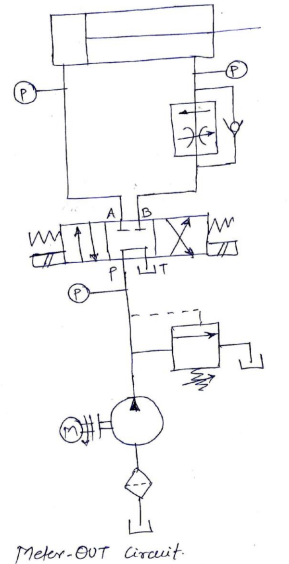
Question:Explain with neat sketch the working of meter out hydraulic circuit.Answer: Meter OUT Circuit A typical meter out circuit is shown in figure. Here the flow control valve is installed in the return line metering the fluid being discharged. In that way, this circuit also gives the control over the actuating speed. But this way of control offers altogether different characteristics to the circuit. Now, the circuit pressure has to overcome the load resistance and the pressure drop across the flow control valve. However, as the flow control valve is on the right side of the piston, the differential area will cause rise in the pressure. This increased pressure helps to overcome the pressure drop across the flow control valve. As the system pressure required will be relatively low, it makes this circuit marginally more efficient on the extend stroke. Initially, the compensatory spool is fully open, and full pump flow is passed into the cylinder until piston moves forward building up pressure at the flow control valve. The compensatory spool will now come into operation and restricts the flow to its correct value. Thus, there is an initial flow surge before the compensatory spool adjusts as in the case of ‘meter-in’ When using meter-out system, the pressure in the rod-end of the cylinder must be carefully considered. With meter-out speed control, the quantity of oil leaving the cylinder is controlled. When the cylinder is extending, the oil from the rod-end is metered which a smaller quantity than that is flowing into the full bore end. Consequently, under extend conditions; meter-out flow control is not as sensitive as meter-in control. When the cylinder is retracting, the reverse is true. Meter-out circuits are best where negative loads may occur, because back pressure is maintained on the exhaust side of the actuator preventing erratic motion. Meter-out circuits provide accurate speed control even with reversing loads. However, as with the meter-in system, considerable heat will be generated when used with a fixed delivery pump and a wide range of piston speeds. Applications: Drilling, Boring, Reaming and tapping operations.
|
| Q 3 d ) |
4 |
Question:Draw the neat sketch of diaphragm clutch and explain its working.Answer:
Diaphragm Spring Type Single Plate Clutch A diaphragm spring type clutch is shown in fig. where shows the clutch in the engaged position and in the disengaged position. It is seen from the above figures that the diaphragm spring is supported on a fulcrum retaining ring so that any section through the spring can be regarded as a simple lever. The pressure plate E is movable axially, but it is fixed radically with respect to the cover. This is done by providing a series of equally spaced lugs cast upon the back surface of the pressure plate. The drive from the engine flywheel is transmitted through the cover, pressure plate and the friction plate to the gear box input shaft. The clutch is disengaged by pressing the clutch pedal which actuates the release fingers by means of a release ring. This pivots the spring about its fulcrum, relieving the spring load on the outside diameter, thereby disconnecting the drive. ----------------------------------------------------------------------------------------------------- |
| Q 3 d ) |
4 |
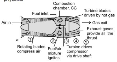
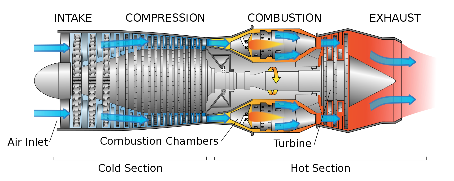
Question:Explain the working principle of turbojet with neat sketch.Answer: Turbojet engine working principle Turbojet engine working principle : shows the schematic of turbojet engine. It has a diffuser section at inlet for realizing some compression of air passing through this section. Due to this air reaching compressor section has pressure more than ambient pressure. This action of partly compressing air by passing it through diffuser section is called “ramming action” or “ram effect”. Subsequently compressor section compresses air which is fed to combustion chamber and fuel is added to it for causing combustion. Combustion products available at high pressure and temperature are then passed through turbine and expanded there. Thus, turbine yields positive work which is used for driving compressor. Expanding gases leaving turbine are passed through exit nozzle where it is further expanded and results in high velocity jet at exit. This high velocity jet leaving nozzle is responsible for getting desired thrust for propulsion.
Turbojet engine working principle is demonstrated below.
The turbojet is an air breathing engine which takes air and then adds heat to it before expanding it. ----------------------------------------------------------------------------------------------------- |
| Q 3 d ) |
4 |
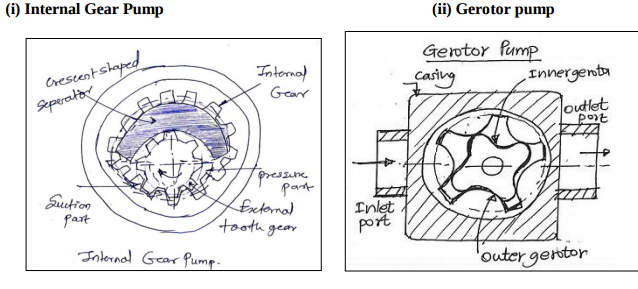
Question:Draw neat labelled sketch of (i) Internal gear pump (ii) Gerotor pumpAnswer:
|
| Q 3 e ) |
4 |
Question:Write the procedure for balancing of a single rotating mass by single masses rotating in the same plane.Answer: Procedure :Balancing of a Single Rotating Mass By a Single Mass Rotating in the Same Plane Consider a disturbing mass m1 attached to a shaft rotating at ω rad/s as shown in Fig. Let r1 be the radius of rotation of the mass m1 (i.e. distance between the axis of rotation of the shaft and the centre of gravity of the mass m1). We know that the centrifugal force exerted by the mass m1 on the shaft, FCl= m1.ω2 . r1 . . . (i) This centrifugal force acts radially outwards and thus produces bending moment on the shaft. In order to counteract the effect of this force, a balancing mass (m2) may be attached in the same plane of rotation as that of disturbing mass (m1) such that the centrifugal forces due to the two masses are equal and opposite.
|
| Q 3 e ) |
4 |
Question:State the advantages of closed cycle gas turbine over open cycle gas turbine (any four).Answer: Advantages of closed cycle gas turbine over open cycle gas turbine: (i) It has higher thermal efficiency for the same minimum and maximum temperature limits and for the same pressure ratio. (ii) Since the heating is external, any kind of fuel even solid fuel having low calorific value may be used. (iii) There is no corrosion due to circulation of combustion product. (iv) As the system is a closed one there is no loss of the working fluid. (v) The size of the turbine will be smaller compared to an open cycle gas turbine of the same output. (vi) The regulation is more simple. (vii) The heat transmission coefficient in the exchanger is better due to the increase in suction pressure. (viii) Loss due to fluid friction is less due to higher Reynolds number. ----------------------------------------------------------------------------------------------------- |
| Q 3 e ) |
4 |
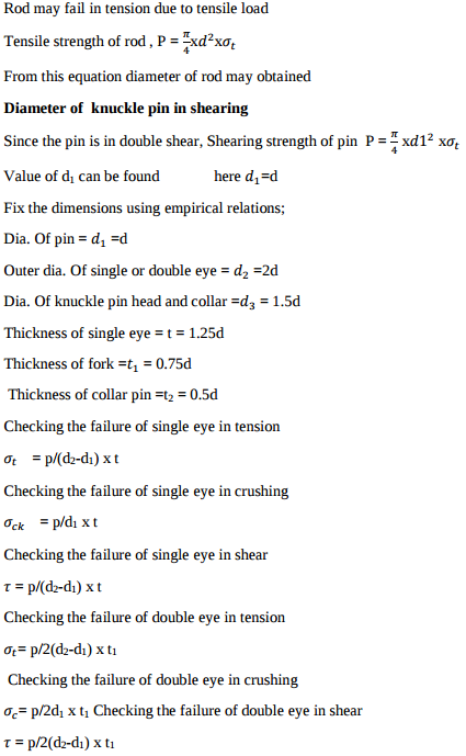
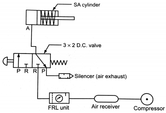
Question:What is FRL ? State the function of each component of FRL.Answer: FRL Unit: It is service unit used in Pneumatic system which is combination of three devices named as Filter, Regulator and Lubricator. Function of FRL unit Filter (F) – 1) To remove the micron and sub-micron particles present in the entering air of compressor. It is Used to separate out contaminants like dust, dirt p[articles from the compressed air Regulator (R) – In pneumatic system the pressure of compressed air may not stable due to possibility of line fluctuation. Hence there is a need to maintain and regulate the air pressure. This function is performing by regulator. Lubricator (L) – Sliding components like spool, a pneumatic cylinder has sliding motion between parts. It may cause friction and wear and tear at mating parts. To reduce friction, lubricating oil particles are added in the compressed air with the help of lubricator. ----------------------------------------------------------------------------------------------------- |
| Q 3 f ) |
4 |
Question:Give detailed classification of followers.Answer: Types of followers The followers may be classified as discussed below: 1. According to the surface in contact. (a)Knife edge follower. When the contacting end of the follower has a sharp knife edge, it is called a knife edge follower. (b) Roller follower. When the contacting end of the follower is a roller, it is called a roller follower. (c) Flat faced or mushroom follower. When the contacting end of the follower is a perfectly flat face, it is called a flat faced follower and when the flat faced follower is circular, it is then called a mushroom follower. (d) Spherical faced follower. When the contacting end of the follower is of spherical shape, it is called a spherical faced follower. 2.According to the motion of the follower. (a) Reciprocating or translating follower. When the follower reciprocates in guides as the cam rotates uniformly, it is known as reciprocating or translating follower. (b) Oscillating or rotating follower. When the uniform rotary motion of the cam is converted into predetermined oscillatory motion of the follower, it is called oscillating or rotating follower. 3. According to the path of motion of the follower. (a) Radial follower. When the motion of the follower is along an axis passing through the centre of the cam, it is known as radial follower (b) Off-set follower. When the motion of the follower is along an axis away from the axis of the cam centre, it is called off-set follower. ----------------------------------------------------------------------------------------------------- |
| Q 4 a ) |
8 |
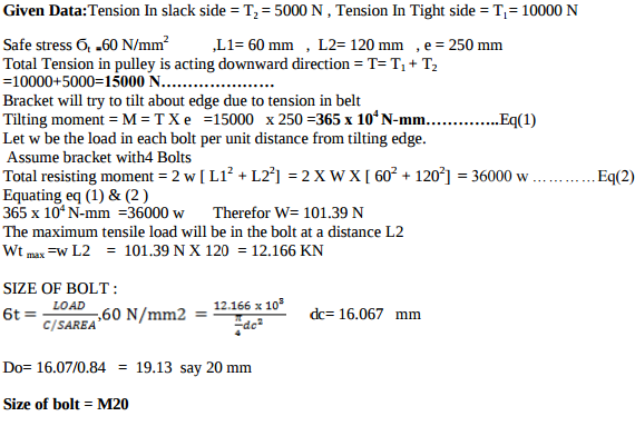
Question:Fig 2 show a C.I. bracket to carryof a shaftAnswer:
|
| Q 4 a ) |
4 |
Question:State advantages and disadvantages of chain drive over belt driveAnswer: Advantages of chain drive over belt drive (Any four) a) No slip takes place in chain drive as in belt drive there is slip. b) Occupy less space as compare to belt drive. c) High transmission efficiency. d) More power transmission than belts drive. e) Operated at adverse temperature and atmospheric conditions. f) Higher velocity ratio. g) Used for both long as well as short distances. Disadvantages of chain drive: 1. Manufacturing cost of chains is relatively high 2. The chain drive needs accurate mounting and careful maintenance 3. High velocity fluctuations especially when unduly stretched 4. Chain operations are noisy as compared to belts ----------------------------------------------------------------------------------------------------- |
| Q 4a)(a) |
4 |
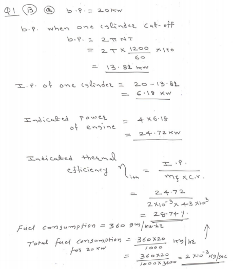
Question:Define the following w.r.to. I.C. engine. i) Indicated power ii) Brake power iii) Volumetric efficiency iv) BSFCAnswer: (i) Indicated Power: The total power developed by combustion of fuel in the combustion chamber is called indicated power. (ii) Brake Power: The power developed by an engine at the output shaft is called brake power. (iii) Volumetric efficiency: It is defined as the ratio of the actual volume of the charge admitted into the cylinder to the swept volume of the piston is known as volumetric efficiency. ( iv) Brake specific fuel consumption: It is the mass of fuel consumed per kw developed per hour, and is a criterion of economical ----------------------------------------------------------------------------------------------------- |
| Q 4a)(a) |
4 |
Question:State the four merits and demerits of using a rubber hose in pneumatic circuit.Answer: Merits: 1)Well equipped with quick connect or disconnect end fitting 2)Can be manufactured in long lengths 3)Capable of withstanding to very high pressures. 4)They can absorb very heavy shocks tha rigid tubes. Demerits: 1) Very poor in abrasion resistance 2) Poor in resisting whether condition. 3) Initial cost is very high 4) They can damage due to incompatible oil ----------------------------------------------------------------------------------------------------- |
| Q 4a)(b) |
4 |
Question:Explain the term swept volume (V s ) w.r.to. i) I.C. engine ii) Reciprocating air compressorAnswer: (i) Swept Volume (VS) w.r.t I.C.Engine: The volume swept through by the piston in moving between top dead centre and bottom dead centre is called swept volume or piston displacement. It is denoted by VS. It is equal to the area of the piston multiplied by its stroke length. Therefore, Swept Volume = π/4xD2 xL Where D = bore of the cylinder in m, and L = stroke length in m. (ii) Swept Volume (VS) w.r.t. Reciprocating air compressor: It is the actual volume of air taken in during suction stroke. It is expressed in m3 . Swept volume when expressed in m3 /min, it is known as piston displacement. ----------------------------------------------------------------------------------------------------- |
| Q 4a)(b) |
4 |
Question:List any four applications of pneumatic rotary actuator. Draw the symbol for variable speed bidirectional air motor.Answer: In all pneumatic power tools like screw drivers, angle grinders, straight grinders. To rotate conveyor belts in food industry. Power device in printing press machine Agitators and mixers Vibrators. symbol for variable speed bidirectional air motor
|
| Q 4a)(c) |
4 |
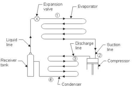
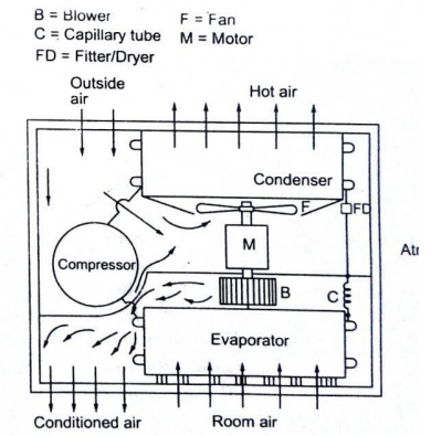
Question:Draw a neat block diagram of vapour compression cycle. Show the direction of flow ofrefrigerant.Answer: Block diagram of Vapour Compression cycle :-
|
| Q 4a)(c) |
4 |
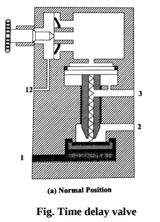
Question:What is the Function of Time Delay valve?Answer: Time delay valve functionTime delay valve function need:Time delay valve function : In certain applications like machining or press operation it is necessary that certain operation be delayed by some fraction even after pressing valve. This objective is achieved by Time delay valve. Time delay valve function working:Time delay valve is a combination valve used to set the operation time as per the requirement. The time delay can be increased or decreased by adjusting the flow through the non-return flow control valve. The change invariably increases or decreases the time taken to fill and pilot actuates the direction control valve. Time delay valve is a combination of a pneumatically actuated 3/2 direction control valve, an air reservoir and a throttle relief valve. The time delay function is obtained by controlling the air flow rate to or from the reservoir by using the throttle valve. Adjustment of throttle valve permits fine control of time delay between minimum and maximum times. In pneumatic time delay valves, typical time delays in the range 5-30 seconds are possible. The time delay can be extended with the addition of external reservoir. Time delay valve, NC type. The constructions of an on-delay timer (NC) type in the normal and actuated are shown in Figure It can be seen that 3/2 DCV operates in the on delay mode permanently. But, in some designs, the valve can be operated in the off-delay mode by connecting the check valve in reverse direction. Time delay valve is shown in diagram below. Time delay valve function diagram:Pneumatic time delay valve is used when time based sequencing is required. Construction and symbol of valve is shown in figure below. It is simply a 3/2 direction control valve, which is impulse operated from one side. Time delaying is achieved by delaying the impulse actuation. The valve has an in-built air reservoir and in-built non-return flow control valve. When impulse is applied to port “Z” for valve actuation, the air passes through needle control valve, which controls the rate of flow, further the valve spool is not actuated until the air reservoir is filled completely and pressure is built-up. (This time difference between impulse application at “Z” and actual spool actuation is the “delay”, which is adjustable through needle valve). This valve is found applicable in time based sequencing, which is common industrial application, e.g. clamping, indexing, feed motions etc.
ALTERNATE DIAGRAM
==================================================== Time delay valve function additional information and Diagrams are given below. ----------------------------------------------------------------------------------------------------- |
| Q 4a)(d) |
4 |
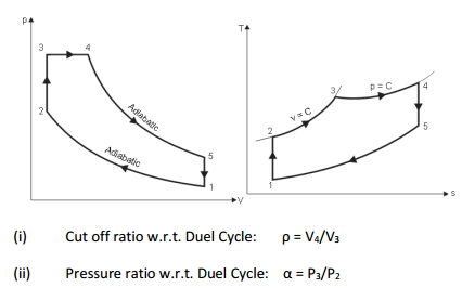
Question:Explain w.r.to. dual cycle i) cutoff ratio ii) pressure ratio.Answer: Duel cycle:
|
| Q 4a)(d) |
4 |
Question:Draw speed control pneumatic circuit for bi-directional air motor.Answer:
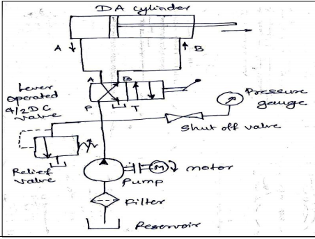
Fig. Speed control of bi-directional air motor Bi-directional air motor rotates in clockwise as well as anti-clockwise direction. The speed of bidirectional motor is controlled as shown in fig. The speed control of motor by using variable two flow control valves having built-in check valve and 4x3 DC valve having zero position or central hold position with lever L1 and L2. When lever L1 is operated, port P will be connected to port A of air motor and motor will start rotating in clockwise direction. Its speed can be controlled by using variable flow control valve F1. Port B of motor will be connected to exhaust R and air in motor will be exhausted through port R via DC valve. When lever L2 is operated, pressure port P will be connected to port B of motor and naturally motor will start rotating in anticlockwise direction. Port A will be connected to port R and air in the motor will be exhausted through port R via DC valve. ----------------------------------------------------------------------------------------------------- |
| Q 4 b ) |
8 |
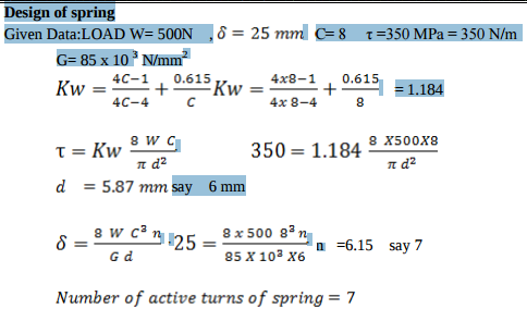
Question:A helical compeersion imperssion speraingAnswer:
|
| Q 4 b ) |
4 |
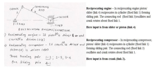
Question:Justify that slider crank mechanism is a modification of the basic four bar mechanism with neat sketch.Answer: Justification for a single slider crank mechanism is a modification of four bar chain mechanism is as given below. 1) Single slider mechanism has four kinematic links – crank, connecting rod, frame and slider and four bar mechanism has crank, coupler, frame and a follower. 2) A follower in four bar mechanism is replaced by a slider. 3) A four bar mechanism has 4 turning pairs and single slider crank mechanism has also four pairs, but one of the turning pairs is replaced by a sliding pairs. 4) A four bar mechanism rotary motion of the crank into oscillating motion of the follower whereas in single slider motion is converted in sliding motion of the piston ----------------------------------------------------------------------------------------------------- |
| Q 4b)(a) |
6 |
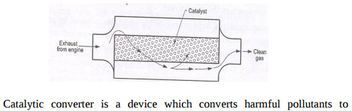
Question:What is meant by catalytic converter ? Briefly explain with the help of neat sketch.Answer: Catalytic converter:
harmless gases. Catalytic converter is used in exhaust emission in control system to convert CO, NOx, HC and other harmful gases to harmless gases. A Catalytic converter consists of a cylindrical unit of small size like a small silencer and is installed into the exhaust system of a vehicle. It is placed between the exhaust manifold and the silencer. Inside the cylindrical tube i.e. converter there is a honey comb structure of a ‘ceramic or metal’ which is coated with ‘alumina base’ material and there after a second coating of precious metals ‘platinum, palladium or rhodium’ or combination of the same. This second coating serves as a catalyst. A catalyst is a substance which causes a chemical reaction intro the gases. When the exhaust gases pass over the converter substance, the toxic gases as CO, HC & NOx are converted into harmless gases as CO2, H2 & N2. ----------------------------------------------------------------------------------------------------- |
| Q 4b)(a) |
6 |
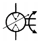
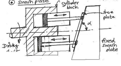
Question:Explain variable displacement axial piston pump with neat sketch.Answer:
Fig. Variable displacement axial piston pump (Sketch 2 Marks and Explanation 2 Marks) Construction and Working: 1. It consists of swash plate which has angular surface with reference to the cylinder block axis. It is used to obtain reciprocating movement of pistons in the cylinder bores. 2. The two or more cylinders are mounted parallel to the axis of driving shaft, the piston rod ends are attached to the angular surface of swash plate with the help of shoe and shoe plate. 3. When driving shaft is rotated it will cause reciprocating movements of pistons in cylinders depending upon the angular surface movement with respect cylinder barrel. 4. It will cause suction of the oil in one cylinder while discharge of high pressure oil in another cylinder. This cycle is repeated for cylinders to give high pressure oil through discharge ports ----------------------------------------------------------------------------------------------------- |
| Q 4b)(b) |
6 |
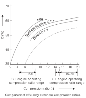
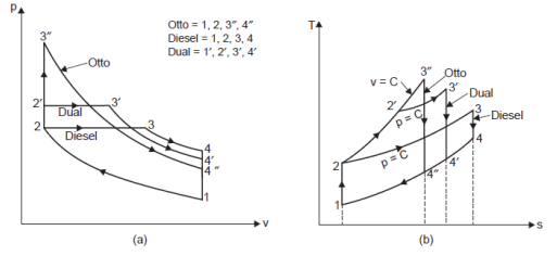
Question:Draw superimposed p-v diagram of Otto cycle, Diesel cycle and Dual cycle to compare their efficiencies for same compression ratio (R c ) and heat rejection (Q r ).Answer: Superimposed P-V Diagram of Otto, Diesel & Duel Cycle: A comparison of the cycles (Otto, Diesel and Dual) on the p-v and T-s diagrams for the same compression ratio and heat supplied is shown in the Fig. Since all the cycles reject their heat at the same specific volume, process line from state 4 to 1, the quantity of heat rejected from each cycle is represented by the appropriate area under the line 4 to 1 on the T-s diagram. As is evident from the cycle which has the least heat rejected will have the highest efficiency. Thus, Otto cycle is the most efficient and Diesel cycle is the least efficient of the three cycles
|
| Q 4b)(b) |
6 |
Question:Explain working of counterbalance hydraulic circuit with neat diagram.Answer: Counterbalance valves are commonly used to counterbalance a weight or external force or counteract a weight such as a platen or a press and keep it from freefalling.Figure1.16 illustrates the use of a counterbalance or back-pressure valve to keep a vertically mounted cylinder in the upward position while the pump idles, that is, when the DCV is in its center position. During the downward movement of the cylinder, the counterbalance valve is set to open at slightly above the pressure required to hold the piston up (a check valve does not permit flow in this direction). The control signal for the counterbalance valve can be obtained from the blank end or rod end of the cylinder. If derived from the rod end, the pressure setting of the counterbalance valve equals the ratio of the load to the annulus area of the piston. If derived from the blank end, the pressure setting equals the ratio of load to the area of piston. This pressure is less and hence usually it has to be derived from the blank end. This permits the cylinder to be forced downward when pressure is applied on the top. The check valve is used to lift the cylinder up as the counterbalance valve is closed in this direction. The directional control valve unloads the pump.
|
| Q 4 c ) |
8 |
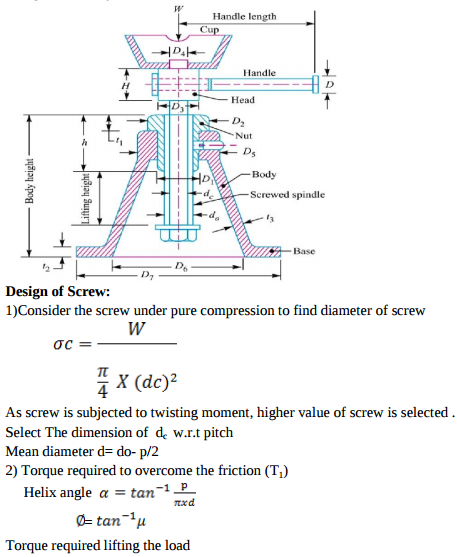
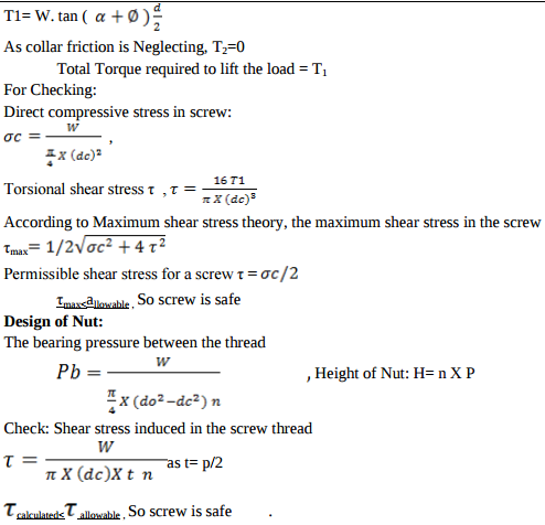
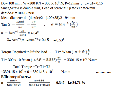
Question:Design of screw jackAnswer:
|
| Q 4 c ) |
4 |
Question:Compare flywheel and governor.Answer: |
| Q 4 d ) |
4 |
Question:Explain with neat sketch construction and working of eddy current dynamometer.Answer: Eddy Current Dynamometer : It consists of a stator on which are fitted a number of electromagnets and a rotor disc made of copper or steel and coupled to the output shaft of the engine. When the rotor rotates, eddy currents are produced in the stator due to magnetic flux set up by the passage of field current in the electromagnets. These eddy currents oppose the motion of the rotor thus loading the engine. The eddy currents are dissipated in producing heat so that this type of dynamometer also requires some cooling arrangements. The torque is measured similar to absorption dynamometers i.e. with the help of moment arm. The load is controlled by regulating the current in the electromagnets. |
| Q 4 e ) |
4 |
Question:A flat foot step bearing 225 mm in diameter supports a load of 7500 N. If the co-efficient of friction is 0.09 and the shaft rotates at 600 rpm, calculate the power lost in friction.Answer: Problem on Foot step bearing D = 225 mm = 0.225 m W = 7500 N µ = 0.09 N = 600 rpm ω = 2 π N / 60 =62.83 rad/sec Uniform pressure condition Frictional torque T = 2/3 µ W R = 50.625 Nm Power lost in friction = T x ω = 50.625 x 62.83 = 3180.8 W --------Ans Uniform wear condition Frictional torque T = 1/2 µ W R = 37.98 Nm Power lost in friction = T x ω = 37.98 x 62.83 = 2385.57 W -------- Ans ----------------------------------------------------------------------------------------------------- |
| Q 4 f ) |
4 |
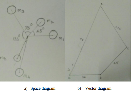
Question:Four masses attached to a shaft and their respective radii of rotation are given as : m 1 = 180 kg m 2 = 300 kg m 3 = 230 kg m 4 = 260 kg r 1 = 0.2 m r 2 = 0.15 m r 3 = 0.25 m r 4 = 0.3 m The angles between successive masses are 45, 75 and 135. Find the position and magnitude of the balance mass required, it its radius of rotation is 0.2 m. The masses revolve in same plane.Answer: Given : m1 = 180 kg, m2 = 300 kg, m3 = 230 kg, m4 = 260 kg r1 = 0.2 m, r2 = 0.15 m, r3 = 0.25 m, r4 = 0.3 m ϴ1 = 45, ϴ2 = 75, ϴ = 135 The centrifugal forces are given by - m1r1 = 36, m2r2 = 45, m3r3 = 57.5, m4r4 = 78
From vector diagram the resultant force is at 60 to the mass m1 and is represented by ar ar = 12 kg m Therefore mb * rb = 12 kgm Balancing mass mb = 12/0.2 = 60 kg at an angle of 2400 with the direction of m1 mass ----------------------------------------------------------------------------------------------------- |
| Q 5 a ) |
8 |
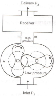
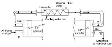
Question:State the methods to improve efficiency of air compressor. Explain two stage air compressor with perfect intercooling with neat sketch.Answer: Following are the methods to improve efficiency of air compressor 1. Cooling cylinder by spraying water during compression stroke. 2. Circulation of water surrounding to cylinder by providing jackets 3. Installing inter cooler between two cylinders 4. Providing greater fins on cylinder 5. By selecting suitable material for cylinder 6. By providing suitable choice of cylinder proportions i.e. short stroke and large bore in construction with sleeve valve Two stage reciprocating air compressor :
Two stage reciprocating compressor Multistage compression refers to the compression process completed in more than one stage i.e. a part of compression occurs in one cylinder ( L.P. cylinder) and subsequently compressed air is sent to subsequent cylinders ( H.P. cylinder) for further compression. Figure shows the schematic of two stage compressor with intercooler between stages. The total work requirement for running this shall be algebraic summation of work required for low pressure (LP) and high pressure (HP) stages. The size of HP cylinder is smaller than LP cylinder as HP cylinder handles high pressure air having smaller specific volume. Intake temp of air at LP =intake temp of air at HP for perfect intercooling. ----------------------------------------------------------------------------------------------------- |
| Q 5 a ) |
8 |
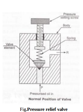
Question:List different types of pressure regulator valves ? Explain any one with neat sketch.Answer: Pressure-relief valve.Pressure-reducing valve. Unloading valve Counterbalance valve Pressure-sequence valve Brake valve.
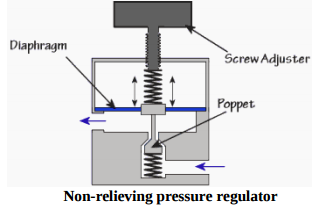
Working: The compressed air pressure from FRL unit acts against the poppet (valve element) through inlet of pressure relief valve. When the force of air is greater than the spring force then poppet gets lifted from the valve seat and valve opens. Thus the excessive pressurized air will get release to the atmosphere through port R. (03 marks) OR Pressure regulation in pneumatics is vital for the correct operation of circuits and for damage prevention to circuit components. As you would imagine all pneumatic components have a maximum operating pressure. Types: A) According to no. of stages Single stage and two stage regulator B) According to pressure relief Non- relieving type and relieving type pressure regulator Non-relieving pressure regulator Non-relieving pressure regulators work by restricting flow rather then venting it should over pressure occur. The regulator restricts flow when the pressure gets too high because the pressure acts on the diaphragm forcing i t up against the spring pressure, the diaphragm has what is called a ‘poppet’ attached on the end of it which is drawn up with the diaphragm and restricts the passing air flow.
|
| Q 5 a ) |
8 |
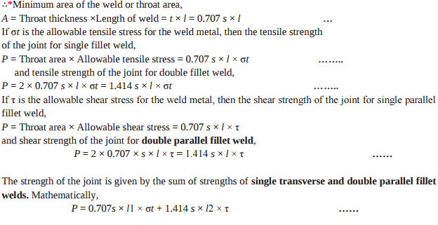
Question:Parallel and transverse WeldAnswer:
|
| Q 5 a ) |
8 |
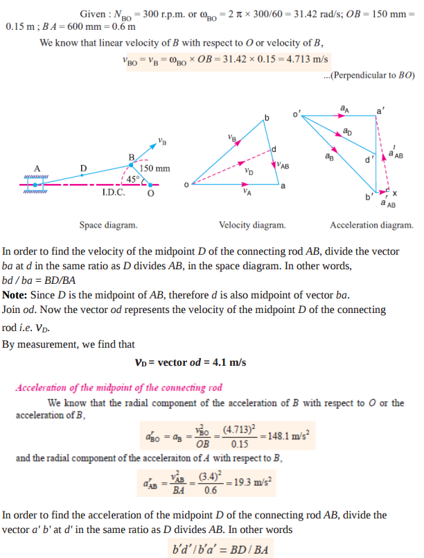
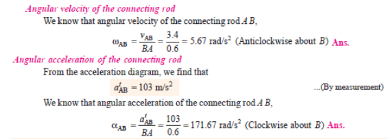
Question:The crank of a slider crank mechanism rotates clockwise at a constant speed of 300 rpm. The crank is 150 mm and the connecting rod is 600 mm long. Determine : (i) linear velocity and acceleration of the mid-point of the connecting rod, and (ii) angular velocity and angular acceleration of the connecting rod, at a crank angle of 45 from inner dead centre position.Answer:
Note: Since D is the midpoint of AB, therefore d' is also midpoint of vector b' a'. Join o' d'. The vector o' d' represents the acceleration of midpoint D of the connecting rod i.e. aD.
By measurement, we find that aD = vector o' d' = 117 m/s2
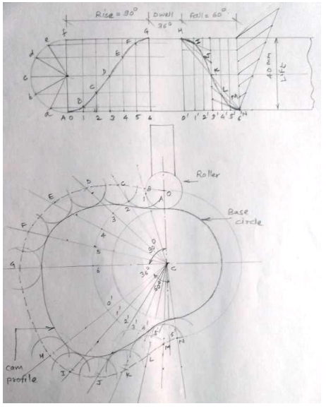
Given: Lift = 40 mm Rise = ¼ x 360 = 900 Fall =1/6 x 360 = 600 Dwell = 1/10 x 360 =360 ----------------------------------------------------------------------------------------------------- |
| Q 5 b ) |
8 |
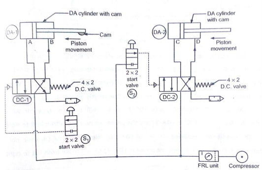
Question:Develop a pneumatic circuit for operation of two DA cylinders such that one operates after other using travel dependant sequencing.Answer: Answer: a pneumatic circuit for operation of two DA cylinders such that one operates after other using travel dependant sequencing as shown in fig. |
| Q 5 b ) |
8 |
Question:State the applications of reciprocating compressor and rotary compressor (4 each).Answer: Applications of Reciprocating Compressor 1. In spray painting shop. 2. In workshop for cleaning machines. 3. For operation of pneumatic tool like rock drill, vibrator etc. 4. In automobile service station to clean vehicle. 5. To drive air motors in coal mines. 6. Food and beverage industry Applications of Centrifugal Compressor 1. In gas turbines and auxiliary power units. 2. In automotive engine and diesel engine turbochargers and superchargers. 3. In pipeline compressors of natural gas to move the gas from the production site to the consumer. 4. In oil refineries, natural gas processing, petrochemical and chemical plants. 5. Air-conditioning and refrigeration and HVAC: Centrifugal compressors quite often supply the compression in water chillers cycles. 6. In air separation plants to manufacture purified end product gases. 7. In oil field re-injection of high pressure natural gas to improve oil recovery. ----------------------------------------------------------------------------------------------------- |
| Q 5 b ) |
8 |
Question:Power Screw: Given DataAnswer:
|
| Q 5 b ) |
8 |
Question:Draw the profile of a cam to raise a valve with S.H.M. through 40 mm in of revolution, keep it fully raised through 1/10 th 1 th 4 revolution and to lower it with uniform acceleration and retardation in 1/6 th revolution. The valve remains closed during the rest of the revolution. The diameter of roller is 20 mm and minimum radius of cam to be 30 mm. The axis of the valve rod passes through the axis of cam shaft.Answer: Fig shows a displacement diagram and a cam profile for the roller follower.
|
| Q 5 c ) |
8 |
Question:List out different pollutants in exhaust gases of petrol and diesel engine ? Briefly explain theireffects on human beings and environments (atleast four).Answer: The major air pollutants emitted by petrol & diesel engines are CO2, CO, HC, NOx, SO2, smoke & lead vapour. Effect of CO: Carbon monoxide combines with hemoglobin forming carboy hemoglobin ,which reduces oxygen carrying capacity of blood. This leads to laziness, exhaustion of body & headache. Prolong exposure can even leads to death. It also affects cardiovascular system, thereby causing heart problem Effect of CO2: Causes respiratory disorder & suffocation. Effect of NOx: It causes respiration irritation, headache, bronchitis, pulmonary emphysema, impairment of lungs, and loss of appetite & corrosion of teeth to human body. Effect of HC: • It has effect like reduced visibility, eye irritation, peculiar odour & damage to vegetation & acceleration the cracking of rubber products. • It induce cancer, affect DNA & cell growth are know a carcinogens. Effect of SO2: It is toxic & corrosive gas, human respiratory track of animals, plants & crops. ----------------------------------------------------------------------------------------------------- |
| Q 5 c ) |
8 |
Question:Explain pneumatic impulse circuit with neat sketch.Answer: Figure 1 shows a symbol circuit of an impulse-valve controlled double acting pneumatic cylinder (A). The position of the impulse-valve (3), which is controlled by the start/stop-valve (1) and the end position valve (2), determines if the cylinder piston shall make a positive stroke and negative stroke. Positive piston stroke is initiated by manual activation of the start valve (1). Negative piston stroking takes place when valve (2) is activated by the cylinder rod at the position a1. ----------------------------------------------------------------------------------------------------- |
| Q 5 c ) |
8 |
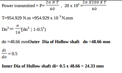
Question:Hollow shaft:Answer:
|
| Q 5 c ) |
8 |
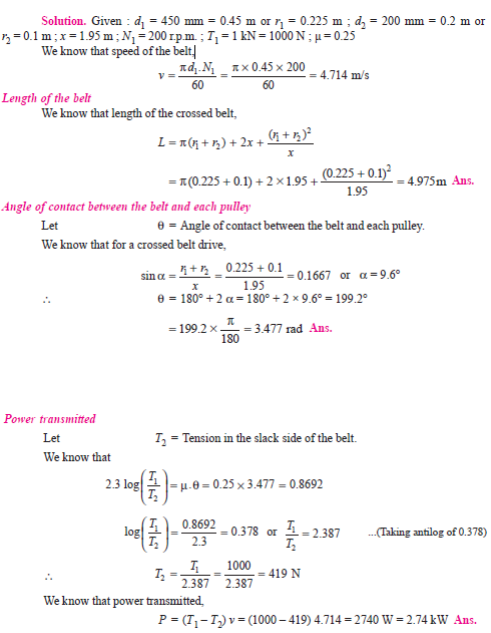
Question:Two pulley, one 450 mm diameter and the other 200 mm diameter are on parallel shafts 1.95 m apart and are connected by a crossed belt. Find the length of the belt required and the angle of contact between the belt and each pulley. What power can be transmitted by the belt when the larger pulley rotates at 200 rpm, if the maximum permissible tension in the belt is 1 kN and the co-efficient of friction between the belt and pulley is 0.25 ?Answer:
|
| Q 6 a ) |
4 |
Question:Explain the following terms :- i) Daltons law of partial pressures ii) Relative humidityAnswer:
|
| Q 6 a ) |
4 |
Question:State at least four advantages and disadvantages of pneumatic systems.Answer: Pneumatic system Advantages DisadvantagesPneumatic system Advantages Disadvantages are given in details below. Pneumatic system Advantages1) Infinite availability of the sourceAir being freely and easily available everywhere there is no scarcity of the source. Just need some filtration for its use in the pneumatic system. As compared to the Hydraulic oil it is very cheap. 2) Safe and cleanAs compared to hydraulic and other systems air is very safe and clean in operation. Food industry, pharmaceuticals industry ect. prefer pneumatic system over other because leakage of air doesn't causes any issues. The system is relatively clean , no dirt accumulates due to oil leakage like in hydraulic system. 3) Less Operating and Maintenance costPneumatic system operates with very less resources and is easy to maintain. 4) The transfer of power and the speed is very easy to set up .The speed and power is controlled by pressure and flow of air, which can be easily controlled by knobbed controls. Just varying the pressure changes the force and varying air flow changes the speed of the actuator. 5) Can be stored and Easy utilized .Compressed air can be easily stored in a reservoir tank. It retains its pressure over long time. Also it is harmless even it leakages. Pneumatic System Disadvantages1) Requires installation of air-producing equipmentEvery pneumatic system needs constent supply of compressed air, which is produced by a compressor. 2) Can easily leakLeakage of air is one of the main issue in pneumatic system. Air can easily leak from the joints and threadings. 3) Potential noiseExhausting air produces large noise as compared to other power transmitting systems. 4) Low operating pressureAs compared to Hydraulic system where the pressure above 500 bar is possible to produce, pneumatic system max pressure is limited in most cases to 10-20 bar. Hence very heavy work can not be done with pneumatic system. ----------------------------------------------------------------------------------------------------- |
| Q 6 a ) |
8 |
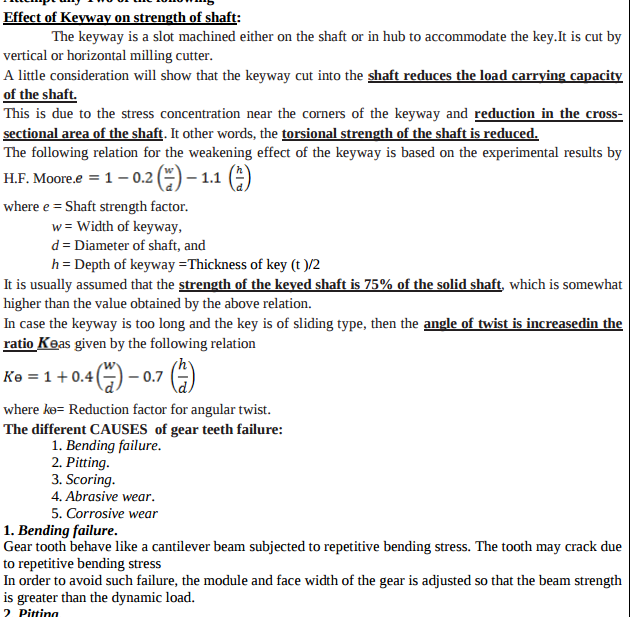
Question:Effect of Keyway on strength of shaftAnswer:
----------------------------------------------------------------------------------------------------- |
| Q 6a)(i) |
8 |
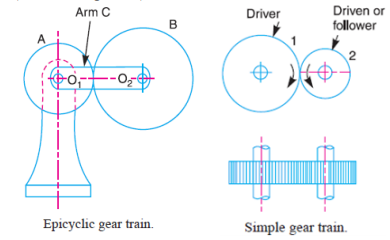
Question:State types of gear train and explain any one.Answer: i) Types of gear trains 1) Simple gear train 2) Compound gear train 2) Epicyclic gear train 4) Inverted gear train Simple gear train. When there is only one gear on each shaft, it is known as simple gear train. The gears are represented by their pitch circles. When the distance between the two shafts is small, the two gears are made to mesh with each other to transmit motion from one shaft to the other Epicyclic gear train: A simple epicyclic gear train is shown in Fig. where a gear A and the arm C have a common axis at O1about which they can rotate. The gear B meshes with gear A and has its axis on the arm at O2, about which the gear B can rotate. If the arm is fixed, the gear train is simple and gear A can drive gear B or vice- versa, but if gear A is fixed and the arm is rotated about the axis of gear A (i.e. O1), then the gear B is forced to rotate upon and around gear A. Such a motion is called epicyclic and the gear trains arranged in such a manner that one or more of their members move upon and around another member are known as epicyclic gear trains. Compound Gear Train When there are more than one gear on a shaft, it is called a compound train of gear. Whenever the distance between the driver and the driven or follower has to be bridged over by intermediate gears and at the same time a great (or much less) speed ratio is required, then the advantage of intermediate gears is intensified by providing compound gears on intermediate shafts
Reverted Gear Train When the axes of the first gear (i.e. first driver) and the last gear (i.e. last driven or follower) are co-axial, then the gear train is known as reverted gear train. We see that gear 1 (i.e. first driver) drives the gear 2 (i.e. first driven or follower) in the opposite direction.
----------------------------------------------------------------------------------------------------- |
| Q 6a)(ii) |
8 |
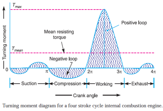
Question:Draw turning moment diagram for single cylinder four stroke I.C. Engine.Answer: ii) Turning Moment Diagram:
----------------------------------------------------------------------------------------------------- |
| Q 6 b ) |
4 |
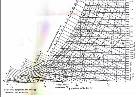
Question:Sketch a psychrometric chart and show the following properties of air on it. i) DBT lines ii) WBT lines iii) Specific volume lines iv) Relative humidity linesAnswer:
|
| Q 6 b ) |
4 |
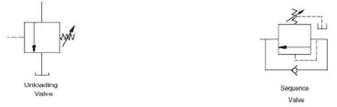
Question:Draw symbol of unloading valve and sequence valve.Answer:
|
| Q 6 b ) |
8 |
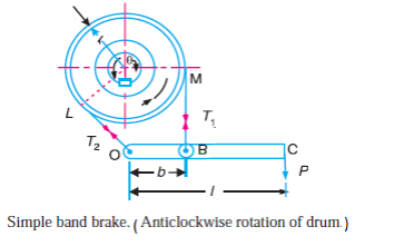
Question:A simple band brake is operated by lever 40 cm long. The brake drum diameter is 40 cm and brake band embrance 5/8 of its circumference. One end of band is attached to a fulcrum of lever while other end attached to pin 8 cm from fulcrum. The co-efficient of friction is 0.25. The effort applied at the end of lever is 500 N. Find braking torque applied if drum rotates anti-clockwise and acts downwards.Answer: Simple band brake:
Given: Length of lever l = 40 cm = 0.4m, diameter d = 40 cm = 0.4, µ = 0.25, b =0 .08 m ϴ = Angle of wrap = 5/8 x 360 = 225 x π /180 = 3.93 rad Braking torque = (T1 –T2) x r T1/T2 = e µϴ = e 0.25 x 3.93 = 2.67 Taking moments about fulcrum P x l = b x T1 500 x 0.40 = 0.08 x T1 T1 = 2500 N T2 = 2500 / 2.67 = 936.3 N Braking Torque = (2500 – 936.3) x 0.2 = 312.74 N-m ----------------------------------------------------------------------------------------------------- |
| Q 6b)(i) |
8 |
Question:Identyfiy the metrial and its compotion A) X10Cr 18 Ni9 Mo 4 Si 2 B) XT72W18Cr4V1:Answer: A) X10Cr 18 Ni9 Mo 4 Si 2 : High Alloy steel having carbon 0.10% , chromium 18%, nickel 9 % ,Molybdenum 4% & silicon 2% B) XT72W18Cr4V1: high speed tool steel having carbon 0.72% ,chromium 4% , tungsten 18% , vanadium 1% ----------------------------------------------------------------------------------------------------- |
| Q 6b)(ii) |
8 |
Question:Design consideration while designing the spur GearAnswer: 1) The power to be transmitted 2) The velocity ration or speed of gear drive. 3) The central distance between the two shafts 4) Input speed of the driving gear. 5) Wear characteristics of the gear tooth for a long satisfactory life. 6) The use of space & material should be economical. 7) Efficiency & speed ratio 8) Cost ----------------------------------------------------------------------------------------------------- |
| Q 6 c ) |
4 |
Question:Draw only a neat labelled sketch of window air-conditioner.Answer: Sketch of window air conditioner
|
| Q 6 c ) |
4 |
Question:Enlist the hydraulic oil manufacturer’s in India.Answer: Castrol-Shell-Indian oil ----------------------------------------------------------------------------------------------------- |
| Q 6 c ) |
8 |
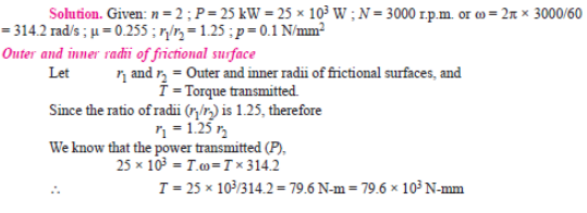
Question:A single plate clutch, effective on both sides, is required to transmit 25 kW at 3000 rpm. Determine the outer and inner radii of frictional surface, if the co-efficient of friction is 0.255 the ratio of radii is 1.25 and the maximum pressure is not to exceed 0.1 N/mm 2 . Also determine the axial thrust to be provided by springs. Assume the theory of uniform wear.Answer:
|
| Q 6c)(i) |
4 |
Question:State any four area of Application of spring:Answer: 1) To cushion, absorb or control energy to external load : Car springs, Railway buffers 2) To store Energy : Watches Toys 3) To Measure forces : Spring Balances, Gauges ,Engines 4) To provide clamping force in Jigs & fixtures. 5) To apply forces as in brakes, clutches & spring loaded valve. ----------------------------------------------------------------------------------------------------- |
| Q 6c)(ii) |
8 |
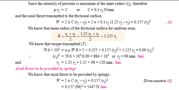
Question:State of the Classification of shaft coupling :Answer:
|
| Q 6 d ) |
4 |
Question:Enlist different uses of compressed air.Answer: Following are the applications of compressed air 1) To drive air motors in coal mines. 2) To inject fuel in air injection diesel engines. 3) To operate pneumatic drills, hammers, hoists, sand blasters. 4) For cleaning purposes. 5) To cool large buildings. 6) In the processing of food and farm maintenance. 7) For spray painting in paint industry. 8) In automobile & railway braking systems. 9) To operate air tools like air guns. 10) To hold & index cutting tools on machines like milling ----------------------------------------------------------------------------------------------------- |
| Q 6 d ) |
4 |
Question:Enlist applications of hydraulic system.Answer: 1 Industrial: Plastic processing machineries, steel making and primary metal extraction applications, automated production lines, machine tool industries, paper industries, loaders, crushes, textile machineries, R & D equipment and robotic systems etc. 2 Mobile hydraulics: Tractors, irrigation system, earthmoving equipment, material handling equipment, commercial vehicles, tunnel boring equipment, rail equipment, building and construction machineries and drilling rigs etc. 3 Automobiles: It is used in the systems like breaks, shock absorbers, steering system, wind shield, lift and cleaning etc. 4 Marine applications: It mostly covers ocean going vessels, fishing boats and navel equipment. 5 Aerospace equipment: There are equipment and systems used for rudder control, landing gear, breaks, flight control and transmission etc. which are used in airplanes, rockets and spaceships. Any four applications ----------------------------------------------------------------------------------------------------- |
| Q 6 e ) |
4 |
Question:State the applications of gas turbine (any four).Answer: Following are the applications of gas turbine 1. It is used for electric power generation. 2. It is used for locomotive propulsion. 3. It is used for ship propulsion. 4. Gas turbine is used in aircrafts. 5. It is used for supercharging for heavy duty Diesel engines. 6. Used in turbo jet and turbo-propeller engine. 7. It is used for various industrial purpose such as in steel industry, oil and other chemical industry. ----------------------------------------------------------------------------------------------------- |
| Q 6 e ) |
4 |
Question:Explain pneumatic circuit for speed control of single acting cylinder with neat sketch.Answer:
Pneumatic cylinders can be directly controlled by actuation of final directional control valve as shown in fig. These valves can be controlled manually or electrically. This circuit can be used for small cylinders as well as cylinders which operates at low speeds where the flow rate requirements are less. When the directional control valve is actuated by push button, the valve switches over to the open position, communicating working source to the cylinder volume. This results in the forward motion of the piston. When the push button is released, the reset spring of the valve restores the valve to the initial position [closed]. The cylinder space is connected to exhaust port there by piston retracts either due to spring or supply pressure applied from the other port. ----------------------------------------------------------------------------------------------------- |
.png)
| Que.No | Marks | ||||||||||||||||
|---|---|---|---|---|---|---|---|---|---|---|---|---|---|---|---|---|---|
| Q a)(ii) |
4 |
Question:Explain single cylinder 4-stroke I.C. engine using turning moment diagram.Answer: A turning moment diagram for a four stroke cycle internal combustion engine, we know that in a four stroke cycle internal combustion engine, there is one working stroke after a crank has turned through two revolution i.e.7200 . Since the pressure inside the engine cylinder is less than the atmospheric pressure during suction stroke therefore a negative loop is formed. During the compression stroke, the work is done on gases, therefore a higher negative loop is obtained.
During the expansion or working stroke, the fuel burns and the gases expand, therefore a positive loop is obtained. In this stroke the work done is by the gases. During exhaust stroke, the work is done on the gases, therefore negative loop is formed. It may be noted that effect of inertia forces on the piston is taken is account. ----------------------------------------------------------------------------------------------------- |
|||||||||||||||
| Q 1a)(a) |
4 |
Question:Represent ‘Brayton Cycle’ on P-V and T-S diagram.Answer:
|
|||||||||||||||
| Q 1a)(b) |
4 |
Question:Define following terms w.r.t. air compressor. i) FAD ii) Compression ratio.Answer: i) FAD – It is the volume of air delivered under the intake conditions of temperature and pressure. ii) Compression ratio – It is defined as the ratio of absolute discharge pressure to the absolute inlet pressure. ----------------------------------------------------------------------------------------------------- |
|||||||||||||||
| Q 1a)(c) |
4 |
Question:Enlist different uses of compressed air.Answer: 1) To drive air motors in coal mines. 2) To inject fuel in air injection diesel engines. 3) To operate pneumatic drills, hammers, hoists, sand blasters. 4) For cleaning purposes. 5) To cool large buildings. 6) In the processing of food and farm maintenance. 7) For spray painting in paint industry. 8) In automobile & railway braking systems. 9) To operate air tools like air guns. 10) To hold & index cutting tools on machines like milling. ----------------------------------------------------------------------------------------------------- |
|||||||||||||||
| Q 1a)(d) |
4 |
Question:Draw ‘Valve timing diagram for 4-stroke cycle diesel engine.Answer:
|
|||||||||||||||
| Q 1a)(i) |
2 |
Question:Enlist the types of constrained motion. Draw a label sketch of any oneAnswer: Types of constrained motion:
|
|||||||||||||||
| Q 1a)(ii) |
2 |
Question:Define (i) Pressure angle (ii) Pitch point related to cam.Answer: (i) Pressure angle: It is the angle between the direction of the follower motion and a normal to the pitch curve. This angle is very important in designing a cam profile. If the pressure angel is too large, a reciprocating follower will jam in its bearing. |
|||||||||||||||
| Q 1a)(iii) |
2 |
Question:How are drives classified?Answer: Classification of drives: |
|||||||||||||||
| Q 1a)(iv) |
2 |
Question:Define: (i) Coefficient of fluctuation of speed. (ii) Coefficient of fluctuation of energy.Answer: (i) Coefficient of fluctuation of speed: Coefficient of fluctuation of speed is defined as the ratio of the maximum fluctuation of speed to the mean speed. It is denoted by C s. N 2 =minimum speed in rpm; N = mean speed in rpm
(ii) Coefficient of fluctuation of energy: Coefficient of fluctuation of energy may be defined as the ratio of the maximum fluctuation of energy to the work done per cycle. It is denoted by Ce. |
|||||||||||||||
| Q 1a)(v) |
2 |
Question:Write any two disadvantages of chain drive.Answer: Disadvantages of chain drives: |
|||||||||||||||
| Q 1a)(vi) |
2 |
Question:Draw line diagram of porter governorAnswer:
|
|||||||||||||||
| Q 1a)(vii) |
2 |
Question:State the application of (i) Disc brake (ii) Internal expanding brakeAnswer: (i) Disc brake: Used in two wheelers as well as in four wheelers. |
|||||||||||||||
| Q 1a)(viii) |
2 |
Question:Why is balancing of rotating parts necessary for high speed engines?Answer: The high speed of engines and other machines is a common phenomenon now-a-days. It |
|||||||||||||||
| Q 1b)(a) |
6 |
Question:Explain in brief, how ‘Morse test’ is carried out ?Answer: First engine is allowed to run at constant speed and brake power of engine is measured when all four cylinder working. (IP1 + IP2 + IP3 + IP4) = (BP) 1234 + (FP) 1234 Where, IP- indicated power. BP – brake power develop. FP – frictional power.
|
|||||||||||||||
| Q 1b)(b) |
6 |
Question:Explain with neat sketch the constructional features of ‘Three Way Catalytic Converter’.Answer:
- Three way convertor uses thin coating of platinum, palladium and rhodium over a support metal (generally alumina) & acts on all three major constituents of exhaust gas pollution i. e. hydrocarbons, carbon monoxide & oxides of nitrogen, oxidizing these to water, carbon dioxide & free hydrogen & nitrogen respectively. - It operates in two stages, the first convertor stage uses rhodium to reduce the NO2 in the exhaust into nitrogen & oxygen. In second stage convertor platinum or palladium acts as oxidation catalyst to change HC & CO into harmless water & CO2. - For supplying the oxygen required in the second stage air is fed into the exhaust after the first stage. - Reactions within catalyst produce additional heat that reaches temperature of 900oC, which is required for the catalytic converter to operate at complete efficiency. To safeguard from this high temperature, the catalytic converter is made of stainless steel &special heat shields are also used. ----------------------------------------------------------------------------------------------------- |
|||||||||||||||
| Q 1b)(i) |
4 |
Question:State inversions of double slider crank chain. Explain Oldham's coupling with neat sketchAnswer: Inversions of double slider crank chain: Oldham’s coupling:
When the driving shaft A is rotated, the flange C (link 1) causes the intermediate piece |
|||||||||||||||
| Q 1b)(ii) |
4 |
Question:Explain: (i) Uniform pressure theory. (ii) Uniform wear theory in clutches and bearing.Answer: (i) Uniform pressure theory: When clutch, bearing become old after being used for a given period, then all |
|||||||||||||||
| Q 1b)(ii) |
6 |
Question:The shaft running at 125 r.p.m. transmits 440 kW. Find the diameter of shaft (d) if allowable shear stress in shaft material is 55 N/mm2 and the angle of twist must not be more than 1 on a length of 16(d). The modulus of rigidity G = 0.80 105 N/mmAnswer:
|
|||||||||||||||
| Q 1b)(iii) |
4 |
Question:Compare cross belt drive and open belt drive on the basis of: (i) Velocity ratio. (ii) Direction of driven pulley. (iii) Length of belt drives (iv) Application.Answer:
----------------------------------------------------------------------------------------------------- |
|||||||||||||||
| Q 1b)(l) |
6 |
Question:What is stress concentration ? State the remedial measures to control the effect of stress concentration with neat sketchesAnswer: i. Stress Concentration: Whenever a machine component changes the shape of its cross-section, the simple stress distribution no longer holds good and the neighborhood of the discontinuity is different. This irregularity in the stress distribution caused by abrupt changes of form is called stress concentration. It occurs for all kinds of stresses in the presence of fillets, notches, holes, keyways, splines, surface roughness or scratches etc.
The presence of stresses concentration cannot be totally eliminated but it can be reduced, so following are the remedial measures to control the effects of stress concentration. 1. Provide additional notches and holes in tension members as shown in fig (a) a)Use of multiple notches. b)Drilling additional holes as shown in fig(b) 2. Fillet radius, undercutting and notch for member in bending. 3. Reduction of stress concentration in threaded members as shown in fig(c) 4. Provide taper cross-section to the sharp corner of member as shown in fig(d)
----------------------------------------------------------------------------------------------------- |
|||||||||||||||
| Q 1 i ) |
4 |
Question:Draw stress-strain diagram for ductile material stating salient pointsAnswer: Stress-Strain diagram for ductile material stating salient points (1 Mark for diagram, 3 Marks for description)
Proportional limit (A): The stress is proportional to strain. Beyond point A, the curve slightly deviates from the straight line. It is thus obvious, that Hooke's law holds good up to point A and it is known as Proportional limit. Elastic limit (B): If the load is increase between point A and B, the body will regain its original shape when load is removed; it means body possesses elasticity up to point B, known as Elastic Limit. Upper yield point (C): If the material is stressed beyond point B, the plastic stage will reach and the material will start yielding known as Upper Yield Point. Lower yield point (D): Further addition of small load drops the stress-strain diagram to point D, as soon as the yielding start, this point ‘D’ is known as Lower yield point. Ultimate stress point (E): After the end of yielding, if the load is increase beyond point ‘D’, there is increase in stresses up to point E and thus maximum value of stresses at point ‘E’ is called as Ultimate Stress point. Breaking Stress point (F): After the specimen has reached the ultimate stress, a neck is formed, which decreases the cross-sectional area of the specimen. The stress corresponding to point F is known as Breaking stress. ----------------------------------------------------------------------------------------------------- |
|||||||||||||||
| Q 1 ii ) |
4 |
Question:Write the design procedure for turn buckle. (Any four steps)Answer: Write any four equation s in the design of turn buckle with relevant sketches
----------------------------------------------------------------------------------------------------- |
|||||||||||||||
| Q 1 iii ) |
4 |
Question:State any four factors to be considered while selecting the coupling.Answer: Following factors should be consider while selecting coupling 1) Cyclic operation 2) Duration or life 3) Misalignment of shafts 4) Required torque and desired speed 5) Direction of rotation 6) Protection against overload 7) Operating conditions ----------------------------------------------------------------------------------------------------- |
|||||||||||||||
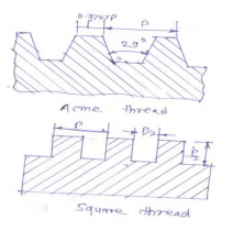
| Q 1 iv ) |
4 |
Question:Why square threads are preferred over V-thread for power transmission ?Answer: . Square threads are preferred over V-thread for power transmission because of following points. 1) Square thread has the greatest efficiency as its profile angle is zero. 2) It produces minimum bursting pressure on the nut. 3) It has more transmission efficiency due to less friction. 4) It transmits power without any side thrust in either direction. 5) It is more smooth and noiseless operation. ----------------------------------------------------------------------------------------------------- |
|||||||||||||||
| Q 2 a ) |
4 |
Question:Draw a labeled sketch of quick return mechanism of shaper and explain its working?Answer: Quick return mechanismQuick return mechanism : Crank and slotted lever quick return motion mechanism. This quick return mechanism is mostly used in shaping machines, slotting machines and in rotary internal combustion engines. In this quick return mechanism, the link AC (i.e. link 3) forming the turning pair is fixed, as shown in fig. The link 3 corresponds to the connecting rod of a reciprocating steam engine. The driving crank CB revolves with uniform angular speed about the fixed centre C. A sliding block attached to the crank pin at B slides along the slotted bar AP and thus causes AP to oscillate about the pivoted point A. A short link PR transmits the motion from AP to the ram which carries the tool and reciprocates along the line of stroke R1R2. The line of stroke of the ram (i.e. R1R2) is perpendicular to AC produced.
n the extreme positions, AP1 and AP2 are tangential to the circle and the cutting tool is at the end of the stroke. The forward or cutting stroke occurs when the crank rotates from the position CB1 to CB2 (or through an angle β) in the clockwise direction. The return stroke occurs when the crank rotates from the position CB2 to CB1 (or through angle α) in the clockwise direction. Since the crank has uniform angular speed,
----------------------------------------------------------------------------------------------------------------------------------------------- Quick return mechanism Alternate answer :
Links - 1.Slider 2. Crank 3.Frame 4.Slotted Lever ----------------------------------------------------------------------------------------------------- |
|||||||||||||||
| Q 2 a ) |
8 |
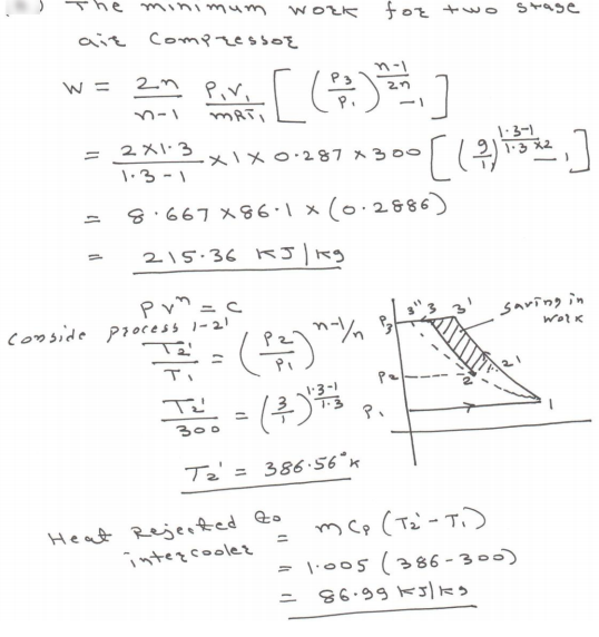
Question:It is desired to compress 15 m3 of air per minute from 1.0132 bar to 10 bar. Calculate minimum power required to drive the compressor having two stages and compared it the power required for single stage compression. Assume value of index for compression process to be 1.3 for both cases also assume the condition for maximum efficiencyAnswer:
|
|||||||||||||||
| Q 2a)(i) |
8 |
Question:State any four factors that govern ‘factor of safety’.Answer: a. Reliability of applied load. b. The extent of simplifying assumptions. c. The certainty as to exact mode of failure. d. Reliability of properties of material and change in these properties during service. e. Extent of stress concentration. f. The reliability of test results to actual machine parts. g. The extent of initial stresses set up during manufacturing. h. The extent of loss of life, if failure occurs. ----------------------------------------------------------------------------------------------------- |
|||||||||||||||
| Q 2a)(ii) |
8 |
Question:Why taper is provided on cotter ? State recommended values of taper.Answer: a. When cotter is driven through the slots, it fit, fight due to wedge action. This ensures tightness of joint in operation and present loosening of the parts. b. Due to taper, it is easy to remove the cotter and dismantle the joint. The normal value of taper varies from 1 in 48 to 01 in 24 and it may increase to 1 in 8 ----------------------------------------------------------------------------------------------------- |
|||||||||||||||
| Q 2 b ) |
4 |
Question:What are the types of kinematic pair ? Give its examples.Answer:
|
|||||||||||||||
| Q 2 b ) |
8 |
Question:Draw neat sketch showing the details of cotter joint. State strength equations for each component with suitable failure cross-sectional area.Answer:
It consist of 3 elements i. Socket ii. Spigot iii. Cotter Where, d= End diameter of rodd1= Diameter of spigot/ID of socket d2= Diameter of spigot collar D1= Outer diameter of socket D2= Diameter of socket collar C=Thickness of socket collar t1= Thickness of spigot collar t= thickness of cotter b= Mean width of cotter a= Distance of end of slot to the end of spigot P= Axial tensile/compressive force σt, σc, τ= Permissible tensile, compressive, shear stress for the component material
|
|||||||||||||||
| Q 2 b ) |
8 |
Question:Represent following processes on Psychrometric chart. i) Heating with humidification ii) Sensible heating. iii) Sensible cooling iv) Evaporative cooling.Answer:
|
|||||||||||||||
| Q 2 c ) |
4 |
Question:Define linear velocity, angular velocity, absolute velocity and state the relation between linear velocity and angular velocity.Answer: Linear Velocity: It may be defined as the rate of change of linear displacement of a body with respect to the time. Since velocity is always expressed in a particular direction, therefore it is a vector quantity. Mathematically, linear velocity, v = ds/dt Angular Velocity: It may be defined as the rate of change of angular displacement with respect to time. It is usually expressed by a Greek letter ɷ (omega). Mathematically, angular velocity, ɷ = dƟ /dt Absolute Velocity: It is defined as the velocity of any point on a kinematic link with respect to fixed point. Relation between v and ɷ: V = r. ɷ Where V = Linear velocity. ɷ = angular velocity. r = radius of rotation. ----------------------------------------------------------------------------------------------------- |
|||||||||||||||
| Q 2 c ) |
8 |
Question:A belt pulley is fastened to a 90 mm diameter shaft running at 300 r.p.m. by means of a key 20 mm wide and 140 mm long. Allowable stress for the shaft and key material are 40 N/mm2 in shear and 100 N/mm2 in crushing. Find the power transmitted and the depth of the key required.Answer:
|
|||||||||||||||
| Q 2 c ) |
8 |
Question:Following observations were made during a trial on 4-stroke, single cylinder engine running at 240 rpm having brake wheel diameter 1.5 meter. Duration of trial 30 min. Fuel consumption 6 liter C.V. of fuel 42000 kJ/kg Sp. gravity 0.8 IMEP 550 kPa Brake load 150 kg Spring balance reading 15 kg Cylinder diameter 30 cm Stroke length 45 cm Jacket cooling water 11 kg/min Temp. rise in jacket water 36°C Determine : i) I.P. and B.P. ii) Heat balance sheet on percentage basis.Answer:
|
|||||||||||||||
| Q 2 d ) |
4 |
Question:Explain the Klein's construction to determine velocity and acceleration of single slider crank mechanism.Answer:
We have already discussed that the velocity diagram for given configuration is a triangle OCP as shown in Fig. If this triangle is rotated through 90°, it will be a triangle oc1 p1, in which oc1 represents VCO (i.e. velocity of C with respect to O or velocity of crank pin C) and is parallel to OC, op1 represents VPO (i.e. velocity of P with respect to O or velocity of cross-head or piston P) and is perpendicular to OP, and c1p1 represents VPC (i.e. velocity of P with respect to C) and is parallel to CP. A little consideration will show that the triangles oc1p1 and OCM are similar. Therefore,
Thus, we see that by drawing the Klein’s velocity diagram, the velocities of various points may be obtained without drawing a separate velocity diagram. Klien’s acceleration diagram: The Klien’s acceleration diagram is drawn as discussed below: 1. First of all, draw a circle with C as centre and CM as radius. 2. Draw another circle with PC as diameter. Let this circle intersect the previous circle at K and L. 3. Join KL and produce it to intersect PO at N. Let KL intersect PC at Q. This forms the quadrilateral CQNO, which is known as Klien’s acceleration diagram. We have already discussed that the acceleration diagram for the given configuration is as shown in Fig. We know that (i) o'c' represents CO ar (i.e. radial component of the acceleration of crank pin C with respect to O ) and is parallel to CO; (ii) c'x represents PC ar (i.e. radial component of the acceleration of crosshead or piston P with respect to crank pin C) and is parallel to CP or CQ; (iii) xp' represents PC at (i.e. tangential component of the acceleration of P with respect to C ) and is parallel to QN (because QN is perpendicular to CQ); and (iv) o'p' represents aPO (i.e. acceleration of P with respect to O or the acceleration of piston P) and is parallel to PO or NO. A little consideration will show that the quadrilateral o'c'x p' is similar to quadrilateral CQNO . Therefore,
|
|||||||||||||||
| Q 2 e ) |
4 |
Question:Draw neat sketch of radial cam with follower and show on it (i) Base circle. (ii) Pitch point. (iii) Prime Circle. (iv) Cam profileAnswer:
|
|||||||||||||||
| Q 2 f ) |
4 |
Question:A shaft runs at 80 rpm & drives another shaft at 150 rpm through belt drive. The diameter of the driving pulley is 600 mm. Determine the diameter of the driven pulley in the following cases: (i) Taking belt thickness as 5 mm. (ii) Assuming for belt thickness 5 mm and total slip of 4%.Answer: Ans.: Given data; N1 = 80 rpm. N2 =150 rpm. D1= 600 mm. S = 4 % To find; D2 =?; (i) Case I: Taking t = 5 mm. Velocity ratio, (V.R.) N2/N1 = (D1 + t)/ (D2 + t) 150/80 = (600 + 5)/ (D2 + 5) Therefore, diameter of driven pulley D2 = 317.66 mm ~ 318mm (ii) Case II: Assuming for belt thickness 5 mm and total slip of 4%. Velocity ratio, (V.R.) N2/N1 = {(D1 + t)/ (D2 + t)} × {1- (S/100)} 150/80 = {(600 + 5) / (D2 + 5)} × {1- (4/100) Therefore, diameter of driven pulley D2 = 304.76 mm ~ 305 mm ----------------------------------------------------------------------------------------------------- |
|||||||||||||||
| Q 3 a ) |
4 |
Question:In a slider-crank mechanism, the crank is 480 mm long and rotates at 20 rad/sec in the counter-clockwise direction. The length of the connecting rod is 1600 mm. when the crank turns 60 from the inner-dead centre. Determine the velocity of the slider by relative velocity method.Answer:
|
|||||||||||||||
| Q 3 a ) |
4 |
Question:State any four advantages of standardization.Answer: i. It saves effort of design of engineers to design and manufacture new machines, as standard components are readily designed by experts. ii. It ensures certain minimum specified quality. iii. It help in manufacturing the components on mass production. iv. Easy and quick replacement of the components is possible. v. Interchangeability of components is possible. vi. It helps in manufacturing the components quickly and economically. vii. Effective utilization of resources. viii. It also contributes to ensure the safety ----------------------------------------------------------------------------------------------------- |
|||||||||||||||
| Q 3 b ) |
4 |
Question:In a slider crank mechanism, crank AB = 20 mm & connecting rod BC = 80 mm. Crank AB rotates with uniform speed of 1000 rpm in anticlockwise direction. Find (i) Angular velocity of connecting rod BC (ii) Velocity of slider C. When crank AB makes an angle of 60 degrees with the horizontal. Draw the configuration diagram also. Use analytical method.Answer:
|
|||||||||||||||
| Q 3 b ) |
4 |
Question:Draw a neat sketch of bell crank lever. Enlist steps in designing the bell crank leverAnswer:
|
|||||||||||||||
| Q 3 b ) |
4 |
Question:Classify gas turbine on the basis of i) working cycle ii) application iii) cycle of operation iv) fuel usedAnswer: 1. On the basis of combustion process a) Constant pressure type b) Constant volume or explosion type 2. On the basis of path of working substance a) Open cycle gas turbine b) Closed cycle gas turbine 3. On the basis of action of expanding gases a) Impulse gas turbine b) Impulse reaction gas turbine 4. On the basis of direction of flow a) Axial flow b) Radial flow ----------------------------------------------------------------------------------------------------- |
|||||||||||||||
| Q 3 c ) |
4 |
Question:Enlist the four effects of subcooling on the performance of V.C.C. refrigeration cycle.Answer:
The process of cooling refrigerant below condensing temperature for a given pressure is known as sub cooling. -Due to sub cooling the refrigerating effect increases or for same refrigerating effect the circulation rate refrigerant decreases and therefore COP of system increases. Thus sub cooling is desirable & is done to increase refrigerating effect & COP of system ----------------------------------------------------------------------------------------------------- |
|||||||||||||||
| Q 3 c ) |
4 |
Question:Explain epicyclic gear train with neat sketch.Answer:
In case of Epicyclic Gear train, the axis of shafts on which gears are mounted may have a relative motion between them, unlike other gear trains. This gives advantage that, very high or low velocity ratio can be obtained compared to simple and compound gear trains; in the small space. In above sketch, if gears A and B are rotating and arm RS is fixed, then it behaves like simple gear train. However, when Arm C rotates and gear A is fixed, then train becomes epicyclic. It is also known as planetary gear train. Applications- Differential gears of the automobiles, back gear of lathe, hoists, pulley blocks ----------------------------------------------------------------------------------------------------- |
|||||||||||||||
| Q 3 c ) |
4 |
Question:Prove that, for a square key, the permissible crushing stress is twice the permissible shear stress.Answer:
|
|||||||||||||||
| Q 3 d ) |
4 |
Question:What is ‘Scavenging’ ? List any two types of ‘scavenging’.Answer: Scavenging: At the end of expansion stroke the combustion chambers of a two stroke engine is left full of products of combustion. This is because unlike four stroke engines, there is no exhaust stroke available to clear the cylinder of burnt gases in two stroke engine the process of clearing the cylinder after the expansion stroke is called scavenging process. The scavenging systems are as follows : 1. Uniform scavenging system 2. Cross scavenging system 3. Loop or reverse scavenging system ----------------------------------------------------------------------------------------------------- |
|||||||||||||||
| Q 3 d ) |
4 |
Question:Draw a labelled sketch of multiplate clutch and state its applications.Answer:
Applications- Automobiles like scooters, motorcycles, textile and paper industries, machine tools ----------------------------------------------------------------------------------------------------- |
|||||||||||||||
| Q 3 d ) |
4 |
Question:Why a coupling should be placed as close to a bearing as possibleAnswer: Coupling should be placed as close to a bearing because of following reasons i. It gives minimum vibrations ii. Bending load on the shaft can be minimized iii. It increases power transmission stability. iv. To avoid deflections of shaft. ----------------------------------------------------------------------------------------------------- |
|||||||||||||||
| Q 3 e ) |
4 |
Question:Explain in brief the importance of ‘Super Charging’.Answer: Supercharging: The power output of an engine depends upon the amount of air inducted in cylinder per unit time, the degree of utilization of this air and the thermal efficiency of the engine. The amount of air inducted per unit time can be increased by increasing the engine speed or by increasing the density of air at intake. As engine speed increases, the inertia load, engine friction, bearing load increases. The method of increasing the inlet air density is called as supercharging. It is usually employed to increase the power output of the engine. The increase of the amount of air inducted per unit time by supercharging is obtained mainly to burn greater amount of fuel in a given engine. Supercharging increases the power output for a given weight and bulk of engine, compensate for loss of power due to altitude and obtain more power from the existing engine ----------------------------------------------------------------------------------------------------- |
|||||||||||||||
| Q 3 e ) |
4 |
Question:Write the procedure of balancing single rotating mass when it balance mass is rotating in the same plane as that of disturbing mass.Answer:
|
|||||||||||||||
| Q 3 e ) |
4 |
Question:Describe ‘bolt of uniform strength’ with neat sketchAnswer: When an ordinary bolt of uniform diameter is subjected to shock load stress concentration across at the weakest part of the bolt i.e. threaded portion (as shown in figure a), it means that greater portion of energy will be absorbed at the region of threaded part and it may cause the failure of threaded portion
There are two methods to achieve bolts of uniform strength i. Turn down shank diameter of bolt equal or lesser than the core diameter of thread (dc) as shown in figure (b) and it gives bolt of uniform strength. ii. In this method an axial hole is drilled to the head as far as threaded portion such that area of shank become equal to the root area of thread as shown in figure (c). Where,d1= Diameter of hole to be drill do= Nominal diameter dc= Core diameter
|
|||||||||||||||
| Q 3 f ) |
4 |
Question:What are the different types of follower motion ? Also draw displacement diagram for uniform velocity.Answer: Different types of follower motions – The follower during its travel may have one of the following motions:- Uniform velocity, Simple harmonic motion, Uniform acceleration and retardation, Cycloidal motion. Displacement Diagram of Uniform Velocity:
----------------------------------------------------------------------------------------------------- |
|||||||||||||||
| Q 4a)(a) |
4 |
Question:Explain in brief the constructional features of MPFI engineAnswer: Absence of Venturi – No Restriction in Air Flow/Higher Vol. Eff./Torque/Power • Hot Spots for Preheating cold air eliminated / Denser air enters • Manifold Branch Pipes not concerned with Mixture Preparation • Better Acceleration Response • Fuel Atomization Generally Improved. • Use of Greater Valve Overlap • Use of Sensors to Monitor Operating Parameters/Gives Accurate Matching of Air/fuel Requirements: Improves Power, Reduces fuel consumption and Emissions • Precise in Metering Fuel in Ports • Precise Fuel Distribution Between Cylinders • Fuel Transportation in Manifold not required so no Wall Wetting • Fuel Surge During Fast Cornering or Heavy Braking Eliminated • Adaptable and Suitable For Supercharging • Increased power and torque. ----------------------------------------------------------------------------------------------------- |
|||||||||||||||
| Q 4a)(b) |
4 |
Question:An engine has piston diameter 15 cm, length of stroke 40 cm and mean effective pressure 5 bar. Engine makes 120 power strokes per minute. Find mechanical efficiency if brake power is 5 kW.Answer:
|
|||||||||||||||
| Q 4a)(c) |
4 |
Question:State any four effect of detonationAnswer: Effects of detonation (1) Noise – As intensity of detonation increases, the sound intensity increases & it is harmful. (2) Mechanical damage – shock waves are so violent that it may cause mechanical damage like breaking of piston. It increases the rate of wear erosion of piston. (3) Pre-ignition – Due to local overheating of spark plug & this pre-ignition increases detonation. (4) Power output & efficiency decreases - Power output & thermal efficiency decreases due to abnormal combustion. (5) Increase in heat transfer – Temperature of cylinder in detonating engine is higher than in non – detonating engine, hence increases the heat transfer. (6) Carbon deposits- Detonation results in increased carbon deposits. ----------------------------------------------------------------------------------------------------- |
|||||||||||||||
| Q 4a)(d) |
4 |
Question:Explain the term w.r.t. I.C. engine. i) Mean Effective Pressure (MEP) ii) Cut off ratio.Answer: ( i ) Mean effective pressure – Defined as the average pressure acting on the piston which will produce the same output as is done by the varying pressure during the cycle. ( ii ) Cut off ratio – Fuel is injected into combustion chamber where only air compressed and is at high temperature. Fuel is injected for a duration of time, say T. The piston would not have reached the bottom dead centre in time T. The fuel is cut off when the volume is, say V2. The clearance volume is V1. The ratio V2/V1 is cut off ratio. ----------------------------------------------------------------------------------------------------- |
|||||||||||||||
| Q 4a)(i) |
4 |
Question:Define Endurance limit and draw typical S-N curve for steel.Answer: Endurance Limit: It is defined as maximum value of the completely reversed bending stress which a polished standard specimen can withstand without failure, for infinite number of cycles (usually 107 cycles).It is known as endurance or fatigue limit (ϭe).
|
|||||||||||||||
| Q 4a)(ii) |
4 |
Question:State the effect of key-way on the strength of shaft with suitable diagramAnswer:
----------------------------------------------------------------------------------------------------- |
|||||||||||||||
| Q 4a)(iii) |
4 |
Question:State any four applications of spring.Answer: 1) To cushion, absorb or control energy to external load : Car springs, Railway buffers 2) To store Energy : Watches Toys 3) To Measure forces : Spring Balances, Gauges ,Engines 4) To provide clamping force in Jigs & fixtures. 5) To apply forces as in brakes, clutches & spring loaded valve. ----------------------------------------------------------------------------------------------------- |
|||||||||||||||
| Q 4a)(iii) |
4 |
Question:State any four advantages and disadvantages of welded joints over riveted joints.Answer: 1. The welded structures are usually lighter than riveted structures. This is due to the reason, that in welding, gussets or other connecting components are not used. 2. The welded joints provide maximum efficiency (may be 100%) which is not possible in case of riveted joints. 3. Alterations and additions can be easily made in the existing structures. 4. As the welded structure is smooth in appearance, therefore it looks pleasing. 5. In welded connections, the tension members are not weakened as in the case of riveted joints. 6. A welded joint has a great strength. Often a welded joint has the strength of the parent metal itself. 7. Sometimes, the members are of such a shape (i.e. circular steel pipes) that they afford difficulty for riveting. But they can be easily welded. 8. The welding provides very rigid joints. This is in line with the modern trend of providing rigid frames. 9. It is possible to weld any part of a structure at any point. But riveting requires enough clearance. 10. The process of welding takes less time than the riveting. Disadvantages 1. Since there is an uneven heating and cooling during fabrication, therefore the members may get distorted or additional stresses may develop. 2. It requires a highly skilled labour and supervision. 3. Since no provision is kept for expansion and contraction in the frame, therefore there is a possibility of cracks developing in it. 4. The inspection of welding work is more difficult than riveting work ----------------------------------------------------------------------------------------------------- |
|||||||||||||||
| Q 4 b ) |
4 |
Question:Justify with neat sketch elliptical trammel as an inversion of double slider crank chain.Answer: Elliptical trammel : Since Elliptical trammel consist of two turning pairs and two sliding pairs, it is inversion of double slider crank chain. This instrument is used for drawing ellipses. This inversion is obtained by fixing a slotted plate (link 4) as shown in fig. It has got two right angled grooves cut into it. 1-2 is turning pair 2-3 is turning pair 1-4 is sliding pair 3-4 is sliding pair.................................. [2 M]
----------------------------------------------------------------------------------------------------- |
|||||||||||||||
| Q 4b)(a) |
6 |
Question:Name any four additives used in lubricants ? State their advantagesAnswer: (1) Detergents – To keep engine parts, such as piston and piston rings, clean & free from deposits. (2) Dispersants – To suspend & disperse material that could form varnishes, sludge etc that clog the engine. (3) Anti – wear – To give added strength & prevent wear of heavily loaded surfaces such as crank shaft rods & main bearings. (4) Corrosion inhibitors – To fight the rust wear caused by acids moisture. Protect vital steel & iron parts from rust & corrosion. (5) Foam inhibitors – control bubble growth, break them up quickly to prevent frothing & allow the oil pump to circulate oil evenly. (6)Viscosity index improver – added to adjust the viscosity of oil. (7) Pour point depressant - improves an oil ability to flow at very low temperature. ----------------------------------------------------------------------------------------------------- |
|||||||||||||||
| Q 4b)(b) |
6 |
Question:A petrol engine working on constant volume cycle has compression ratio of 8 and consume 1 kg of air per minute, if minimum and maximum temp. during cycle is 300 °K and 2000 °K respectively. Find power developed by engine. Assume γ = 1.4 and Cv = 0.71 kJ/kg °K.Answer:
|
|||||||||||||||
| Q 4b)(i) |
6 |
Question:Describe the importance of aesthetic considerations in design related to shape, colour and surface finish.Answer: 1) The shape should not be like blocks but various forms like sculpture, streamlined, aerodynamic, taper should be used. 2) The component should be symmetrical at lean about one axis. 3)proper shape of a product help to make the product more attractive. 4) The shape of the product should be regular, even & proportionate Regarding Colour: ……….Any 2 pt : 1 M Each 1) The colour and shape of component should be such that in should attract appeal and impress customer. 2) The colour should match with conventions, moods e.g. red for danger, gray for dull, yellow for cautions, green for safe etc. 3) Too bright colour should be avoided. 4) The colour should be compatible with conventional ideas of the operator. Regarding Surface finish ……….Any 2 pt : 1 M Each 1) Products with better surface finish are always aesthetically pleasing’ 2) The surface coating processes like spray painting, anodizing, electroplating etc greatly the aesthetic appeal of product ----------------------------------------------------------------------------------------------------- |
|||||||||||||||
| Q 4b)(ii) |
6 |
Question:State any six design considerations while designing the spur gearAnswer: 1) The power to be transmitted 2) The velocity ration or speed of gear drive. 3) The central distance between the two shafts 4) Input speed of the driving gear. 5) Wear characteristics of the gear tooth for a long satisfactory life. 6) The use of space & material should be economical. 7) Efficiency & speed ratio 8) Cost ----------------------------------------------------------------------------------------------------- |
|||||||||||||||
| Q 4 c ) |
4 |
Question:Differentiate between flywheel and governor.Answer: Difference between Flywheel and Governor :
|
|||||||||||||||
| Q 4 d ) |
4 |
Question:Explain construction and working of eddy current dynamometer.Answer: Construction and Working of Eddy current dynamometer : |
|||||||||||||||
| Q 4 e ) |
4 |
Question:A multiplate disc clutch transmits 55 kW of power at 1800 rpm. Coefficient of friction for the friction surfaces is 0.1. Axial intensity of pressure is not to exceed 160 kN/m2 . The internal radius is 80 mm and is 0.7 times the external radius. Find the number of plates needed to transmit the required torque.Answer:
|
|||||||||||||||
| Q 4 f ) |
4 |
Question:A rotor having the following properties : m1 = 4 kg r1 = 75 mm θ1 = 45o m2 = 3 kg r2 = 85 mm θ2 = 135o m3 = 2.5 kg r3 = 50 mm θ3 = 240o Determine the amount of the countermass at a radial distance of 75 mm required for the static balance.Answer: Data :
|
|||||||||||||||
| Q 5 a ) |
8 |
Question: Answer:
Calculations: i) Velocity of crank AO: VAO = (r X ω ) X (480 X 20)
aab = l(ab) X Scale = 4.3 X 40 X 103 aab = 172 X 10 mm/sec2 ----------------------------------------------------------------------------------------------------- |
|||||||||||||||
| Q 5 a ) |
8 |
Question:A screw jack is used to lift a load of 50 kN through a maximum lift of 200 mm. The material used for a screw is steel of allowable stresses in tension and compression as 100 N/mm2 and 50 N/mm2 respectively. The pitch of screw is 8 mm. The nut is made of phosphor bronze with allowable stresses as 50 N/mm2 and 45 N/mm2 in tension and crushing. The allowable shear stress for nut material is 40 N/mm2 . The allowable bearing pressure between nut and screw is not to exceed 20 N/mm2 . If the coefficient of friction between screw and nut is 0.14, design the screw and nutAnswer:
|
|||||||||||||||
| Q 5 a ) |
8 |
Question:Explain with neat block diagram the working of ‘Vapour Absorbtion Cycle’.Answer: Working of Simple Vapor absorption system: A Simple Vapor absorption system consists of evaporator, absorber, generator, condenser, expansion valve, pump & reducing valve. In this system ammonia is used as refrigerant and solution is used is aqua ammonia. Strong solution of aqua ammonia contains as much as ammonia as it can and weak solution contains less ammonia. The compressor of vapor compressor system is replaced by an absorber, generator, reducing valve and pump. The heat flow in the system at generator, and work is supplied to pump. Ammonia vapors coming out of evaporator are drawn in absorber. The weak solution containing very little ammonia is spread in absorber. The weak solution absorbs ammonia and gets converted into strong solution. This strong solution from absorber is pumped into generator. The addition of heat liberates ammonia vapor and solution gets converted into weak solution. The released vapor is passed to condenser and weak solution to absorber through a reducing valve. Thus, the function of a compressor is done by absorber, a generator, pump and reducing valve. The simple vapor compressor system is used where there is scarcity of Electricity and it is very useful at partial and full load. -------
|
|||||||||||||||
| Q 5 a ) |
4 |
Question:State and explain Law of Gearing.Answer: Law of GearingLaw of gearing states that the common normal at the point of contact between a pair of teeth must always pass through the pitch point for all positions of mating gear. This law forms the basis for the gear profile design. This is a must condition for the two gears to perform properly. Law of gearing ProofConsider the portions of two gear teeth in mesh.o1 and o2 are centre points, Let K= point of contact TT = COmmon tangent at the point of contact K N'N' = common tangent at the pont of contact K O1m and O2N are perpendicular to common normal N'N'.
Law of gearing animationAs shown in the diagram below the common normat at the point of contact between a pair of teeth must always pass through the pitch point for all positions of mating gears. This is the fundamental condition which must be satisfied while designing the profiles of teeth for gears.
This law is must for a gearing pair to perform properly. The animation clearly demonstrates the blue line which traces the path of the point of contact.
Link to other topics of Theory of machines is given below.
----------------------------------------------------------------------------------------------------- |
|||||||||||||||
| Q 5 b ) |
8 |
Question:Draw the profile of cam operating a roller reciprocating follower with the following data : Minimum radius of cam = 25 mm lift = 30 mm Roller diameter = 15 mm The cam lifts the follower for 120owith SHM followed by a dwell period of 30o. Then the follower lowers down during 150o of the cam rotation with uniform acceleration and deceleration followed by a dwell period.Answer:
ii) cam profile:
|
|||||||||||||||
| Q 5 b ) |
8 |
Question:A railway wagon having 1500 kg mass and moving at 1 m/s velocity dashes against a bumper consisting of two helical springs of spring index 6. The springs, which get compressed by 150 mm while resisting a dash made of spring steel having allowable shear stress of 360 N/mm2 and modulus of rigidity 8.4 104 N/mm2 . Design the helical coil spring with circular crosssection of spring wire.Answer:
----------------------------------------------------------------------------------------------------- |
|||||||||||||||
| Q 5 b ) |
8 |
Question:What do you mean by ‘Perfect Intercolling’ ? Explain with the help of P.V. diagram.Answer: Intercooling : In perfect intercooling the temperature of air after passing out of intercooler is same as that of the temperature of air before compression of LP cylinder.
|
|||||||||||||||
| Q 5 c ) |
8 |
Question:Two parallel shafts, connected by a crossed belt, are provided with pulleys 480 mm and 640 mm in diameters. The distance between the centre lines of the shafts is 3 m. Find by how much the length of the belt should be changed if it is desired to alter the direction of rotation of the driven shaft.Answer:
|
|||||||||||||||
| Q 5 c ) |
8 |
Question:Explain the working of ‘Turbo-Prop’ engine with neat sketch.Answer: The main components of turbo-prop engine are a propeller, gear reduction unit, a compressor, a combustor, gas turbine and the nozzles. In this engine 80 to 90% of the total propulsive thrust is generated by the gas turbine and the remainder is developed by the expansion of the gases in nozzles. Due to this the power generated in the gas turbine is used for driving the compressor and the propeller, while in case of turbojet engines the turbine power is only used to drive the compressor and the auxiliaries. The gas turbine drives the propeller through the reduction gear unit and it draws a large amount of air. A large part of this air drawn by the propeller is passed through the ducts around the engine and the remainder is compressed in the diffuser by ram compression and further in the compressor. Fuel is burnt in the combustor and the resultant high temperature gases are expanded in the turbine and finally in the nozzles. The total thrust developed is the sum of thrust developed by the propeller and the nozzle. Unlike the turbojet engines the turboprop engines are widely used for commercial and military air crafts, due to their low specific fuel consumption and high flexibility of operation at reasonably high speed.
|
|||||||||||||||
| Q 5c)(i) |
8 |
Question:Show that the efficiency of self locking screw is less than 50%Answer:
|
|||||||||||||||
| Q 5c)(ii) |
8 |
Question:State any four advantages of ball bearings over plain journal bearings.Answer: 1) The ball bearings have a far smaller contact area and thus have a lower frictional drag coefficient. 2) Due to less frictional drag means better response and less power consumption. 3) The turbo can spool up much faster, which reduces turbo-lag and offers a major performance advantage over journal bearing turbochargers at lower to mid turbocharger speeds. 4) The reduced contact area of the ball bearings means that it requires far less lubrication, allowing for lower oil pressure feeds. 5) The ball bearing more reliable. 6) Less expensive. 7) Ball bearings generate less heat and require simple and inexpensive lubrication - by oil ring, oil mist, or oil bath method. ----------------------------------------------------------------------------------------------------- |
|||||||||||||||
| Q 6 ) |
4 |
Question:Draw a neat sketch of leaf spring of semi-elliptical type and name its parts.Answer: Sketch of Leaf Spring of semi elliptical Type ….Diagram+ Names :
|
|||||||||||||||
| Q 6 a ) |
4 |
Question:State the following term : i) Tonnes of refrigeration ii) COPAnswer:
|
|||||||||||||||
| Q 6a)(i) |
4 |
Question:Explain steep and creep phenomenon in belts.Answer: Slip of Belt:- Ans:- When driver pulley rotates firm grip between its surface and the belt. This firm grip between pulley and belt is because of friction and known as frictional grip. If this frictional grip becomes insufficient to transmit the motion of pulley to belt. Then there will be. 1) Forward motion of driver pulley without carrying belt called as slip on driving side. 2) Some forward motion of belt without carrying driven pulley this is called as slip on driver side. The difference between linear speed of rim of pulley and belt on the pulley is known as slip of belt. The velocity ratio considering slip is given by:-
Creep of Belt:- The belt moves from driving pulley is known as Tight side and belt moves from driving pulley to driver pulley as slack side. Tension on both i.e. on tight sides and slack side is not equal ( T1> T2 ) . The belt material is elastic material which elongates more on Tight side than the slack side resulting in unequal stretching on both sides of drive. A certain portion of belt when passes from slack side to tight side extends and certain portion of belt when contracts, passes from tight side to slack side because of relative motion. The relative motion between belt and pulley surface due to unequal stretching of two sides of drives is known as creep. ----------------------------------------------------------------------------------------------------- |
|||||||||||||||
| Q 6a)(ii) |
4 |
Question:Explain single cylinder 4-stroke I.C. engine using turning moment diagram.Answer: A turning moment diagram for a four stroke cycle internal combustion engine, we know that in a four stroke cycle internal combustion engine, there is one working stroke after a crank has turned through two revolution i.e.7200 . Since the pressure inside the engine cylinder is less than the atmospheric pressure during suction stroke therefore a negative loop is formed. During the compression stroke, the work is done on gases, therefore a higher negative loop is obtained.
During the expansion or working stroke, the fuel burns and the gases expand, therefore a positive loop is obtained. In this stroke the work done is by the gases. During exhaust stroke, the work is done on the gases, therefore negative loop is formed. It may be noted that effect of inertia forces on the piston is taken is account. ----------------------------------------------------------------------------------------------------- |
|||||||||||||||
| Q 6 b ) |
8 |
Question:A simple band brake shown in figure 2 is applied to a shaft carrying a flywheel of mass 250 kg and of radius of gyration 300 mm. The shaft speed is 200 rpm. The drum diameter is 200 mm and the coefficient of friction is 0.25. The dimensions a and l are 100 mm and 280 mm respectively and the angle β = 135o. Determine (i) the brake torque when a force of 120 N is applied at the lever end. (ii) the number of turns of the flywheel before it comes to rest. (iii) the time taken by flywheel to come to rest.Answer: A simple band brake drum:
|
|||||||||||||||
| Q 6 b ) |
4 |
Question:Why majority of air compressors available in the market are multi staged ? ExplainAnswer: Multi-stage air compressors feature many benefits and so, they are mostly used in the market. Some of those features are given below 1. Higher air pressures are achievable by multi-staging (about 175 PSI against 120 PSI in single stage) 2. It requires less power for running 3. Light weight cylinders can are used 4. Leakages are less 5. Overall discharge temperatures are lower 6. Intercooler increases the efficiency of unit 7. It has a greater durability 8. Many multi-stage air compressors have the crankcase cast separate from the pump cylinders, which makes it easier to repair. 9. Multi-stage compressors Air compressors can perform (are suitable) many different functions in industrial applications ----------------------------------------------------------------------------------------------------- |
|||||||||||||||
| Q 6 b ) |
4 |
Question:Explain different forms of threads with their relative advantages and applications.Answer: Square threadsSquare threads are the most commonly used thread form for the power screws. Following table gives you various thread forms and comparisons.
Sq. threads Advantages and disadvantagesThe advantages of sq. threads are as follows: 1) Efficiency of sq. threads is more than trapezoidal threads 2) There is no side thrust or radial pressure. The disadvantages of sq. threads are, 1) Sq. threads are difficult to manufacture than trapezoidal threads. 2) The wear of sq. threads can not be compensated as it can be done in trapezoidal. 3) The thread thickness at core is less than trapezoidal, hence sq. threads have less load carrying capacity. Square threads and other forms diagrams
|
|||||||||||||||
| Q 6 c ) |
8 |
Question:A conical pivot with angle of cone as 100o, supports a load of 18 kN. The external radius is 2.5 times the internal radius. The shaft rotates at 150 rpm. If the intensity of pressure is to be 300 kN/m2 and coefficient of friction as 0.05, what is the power lost in working against the friction ?Answer:
|
|||||||||||||||
| Q 6 c ) |
4 |
Question:Represent Carnot cycle on P-V and T-S diagramAnswer:
|
|||||||||||||||
| Q 6 c ) |
4 |
Question:Determine the size of bolt in the cylinder head of a steam engine. The engine cylinder has a bore of 400 mm and the maximum steam pressure to which the cylinder is subjected is 1.5 N/mm2 . Cylinder head is held on the cylinder by 16 number of bolts. The permissible tensile stress for the bolt material is 25 N/mm2Answer:
Bolt size will be M 30 or M32 ----------------------------------------------------------------------------------------------------- |
|||||||||||||||
| Q 6 d ) |
4 |
Question:Compare between window air conditioner and split air conditioner (any four)Answer:
|
|||||||||||||||
| Q 6 d ) |
4 |
Question:State any four disadvantages of rolling bearings as compared to journal bearingsAnswer: Disadvantages of rolling bearing as compared to Journal Bearing: 1) Initial cost is very high 2) Noisy in normal operation. 3) Shock capacity is less. 4) Finite life due to failure by fatigue. 5) Dirt & metal chips can enter the bearing & may lead it to failure. 6) Occupies greater diametral space compared to journal bearing. ----------------------------------------------------------------------------------------------------- |
|||||||||||||||
| Q 6 e ) |
4 |
Question:Explain any one method to improve thermal efficiency of gas turbine with the help of block diagram.Answer:
----------------------------------------------------------------------------------------------------- |
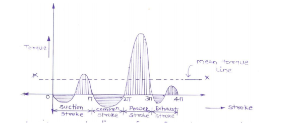
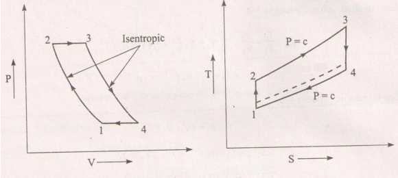
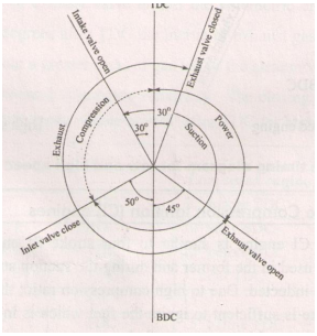
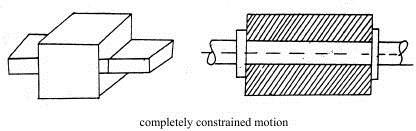
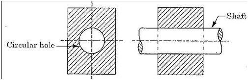
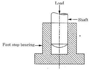
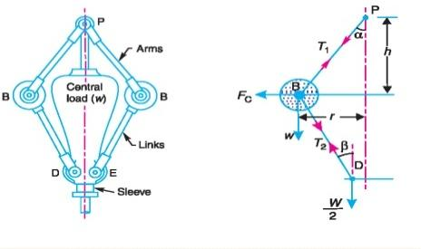
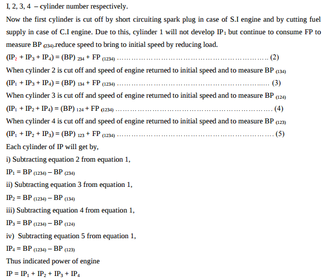
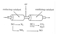
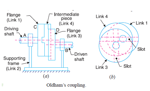
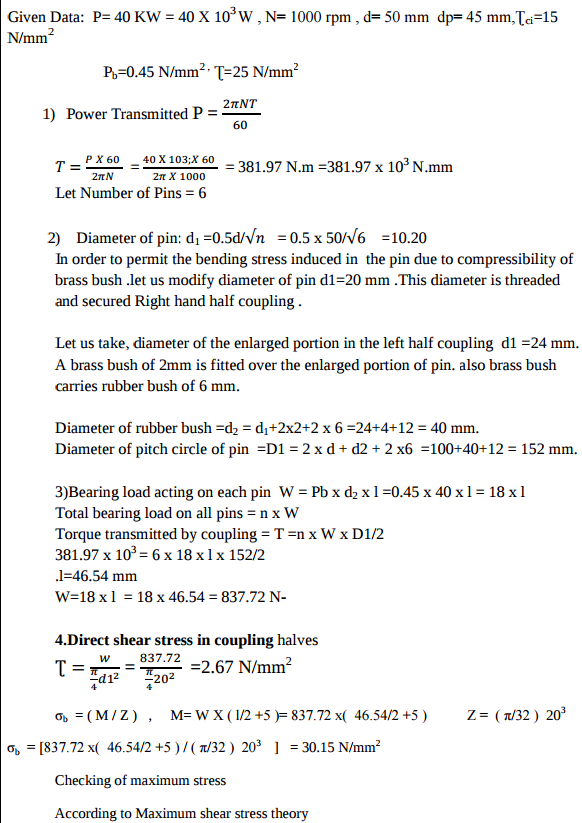
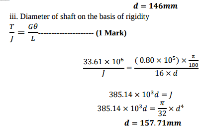
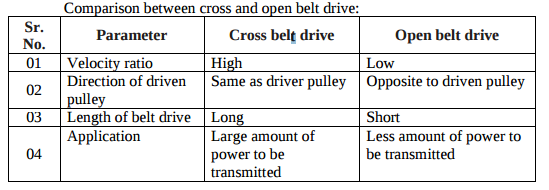
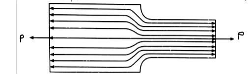
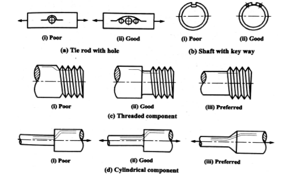
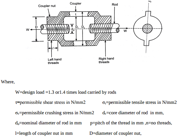
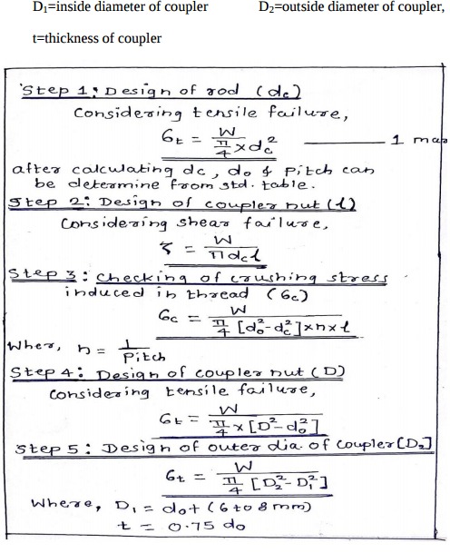
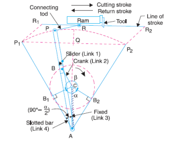
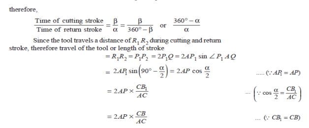
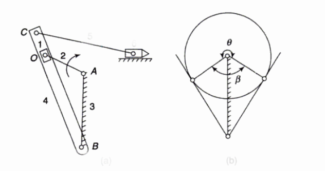
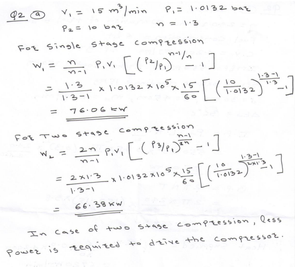

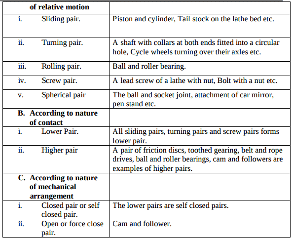
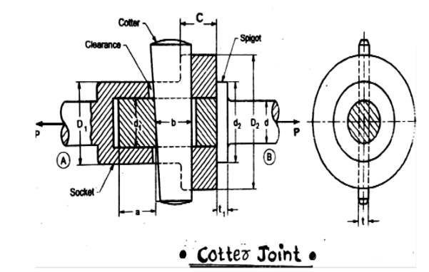
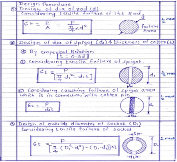
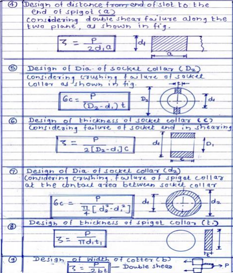
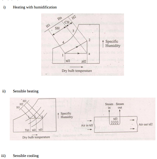
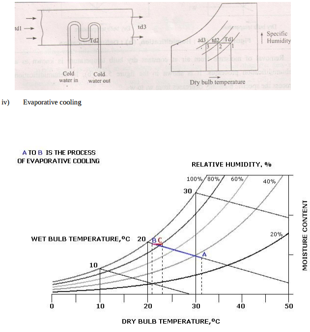
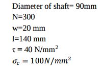
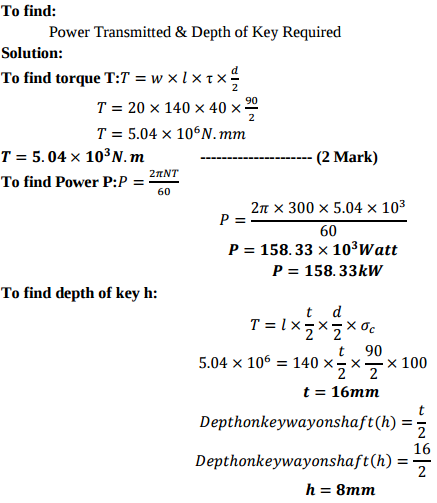
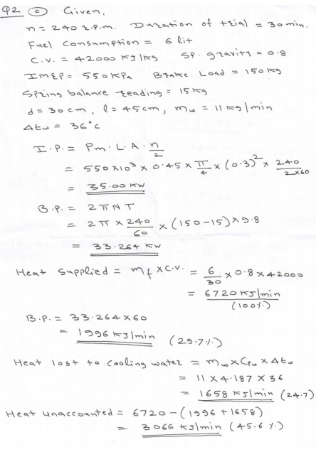
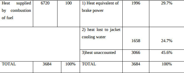
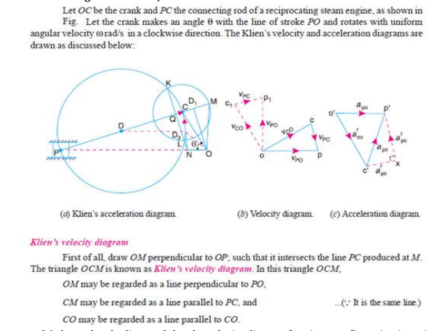
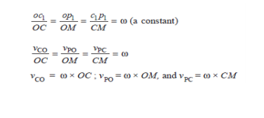
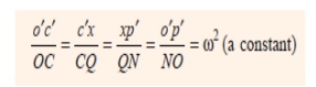
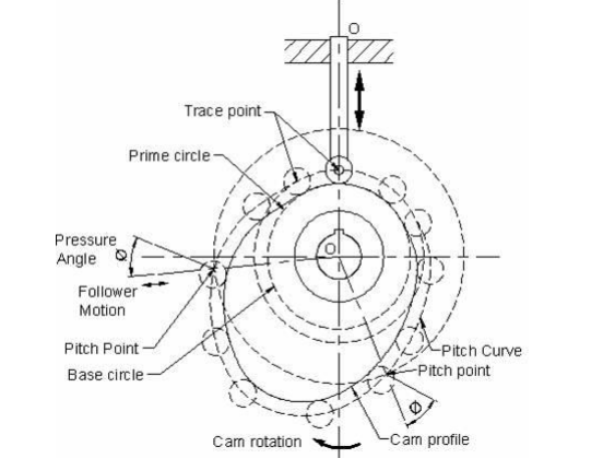
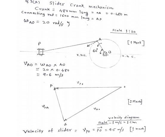
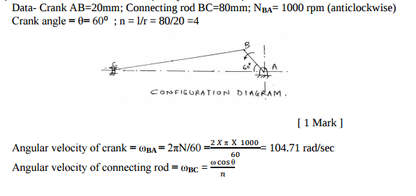
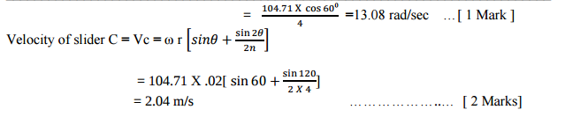
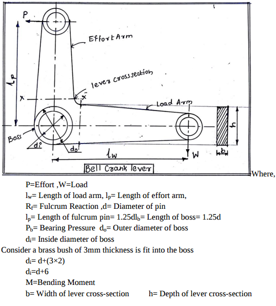
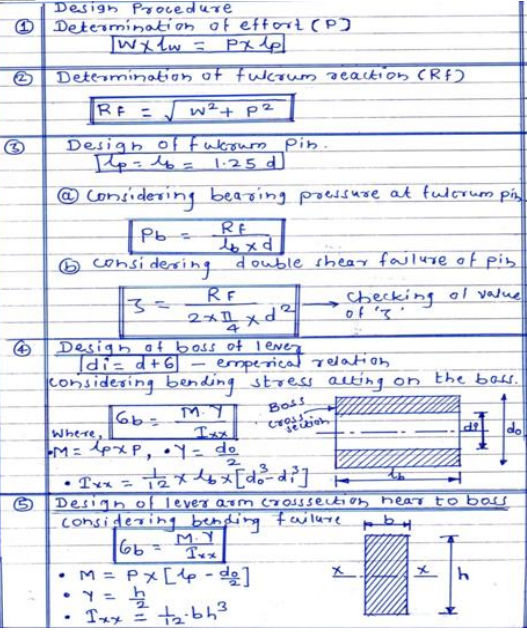
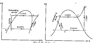
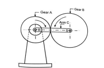
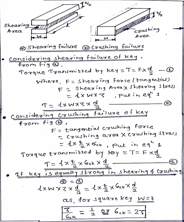
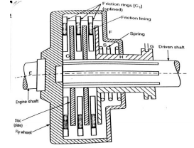
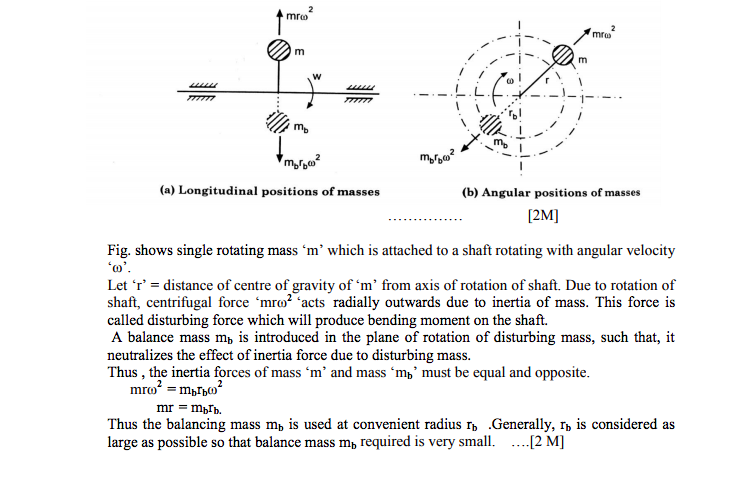
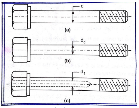
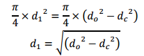
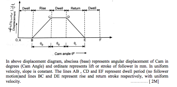
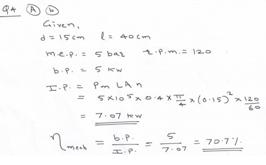
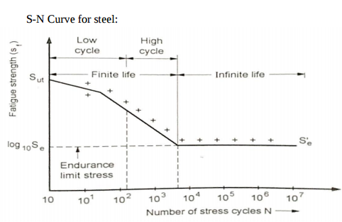
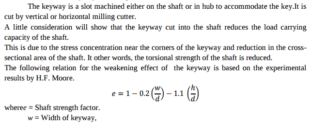 +
+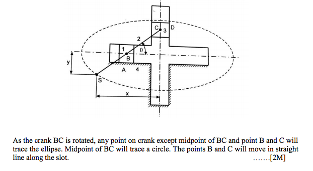
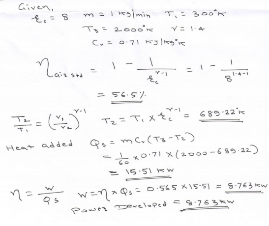
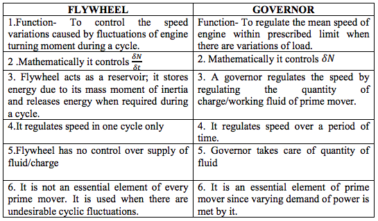
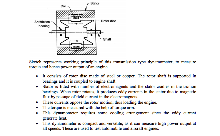
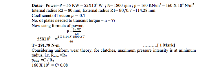
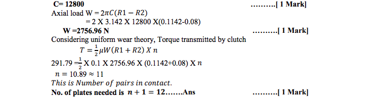
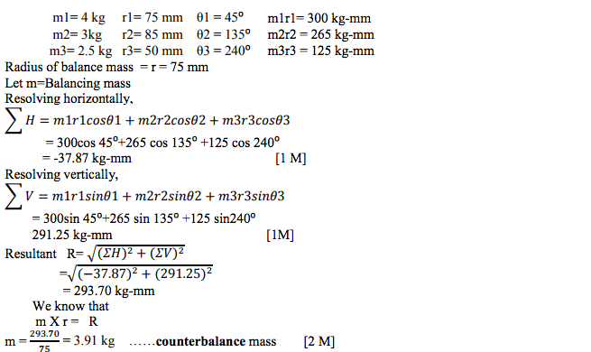
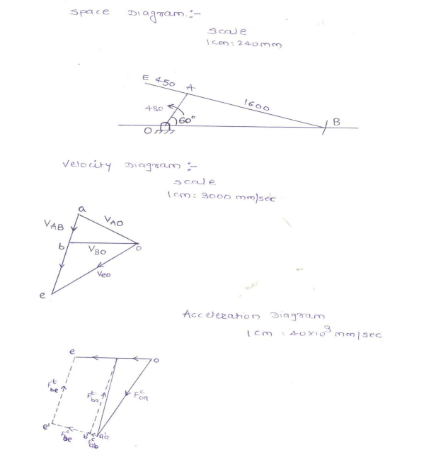
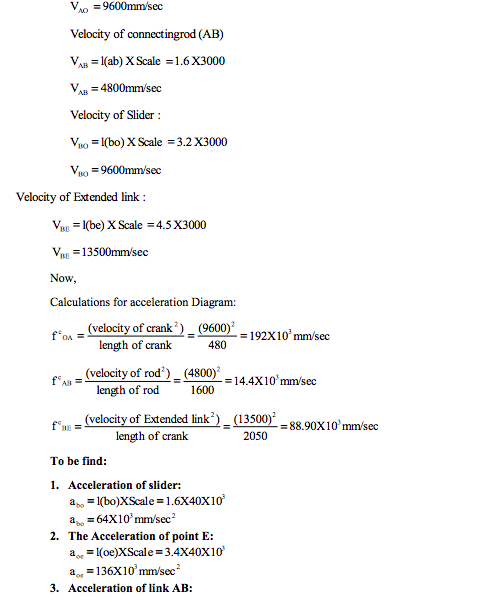
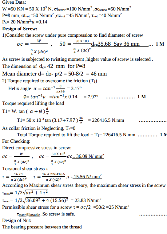
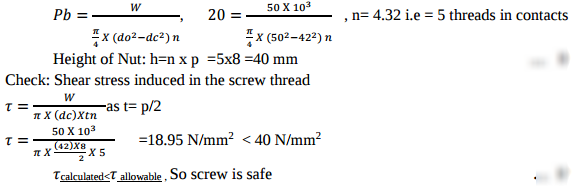
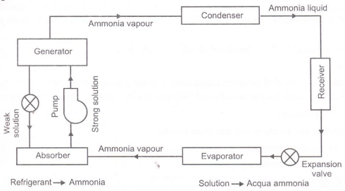
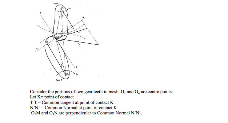
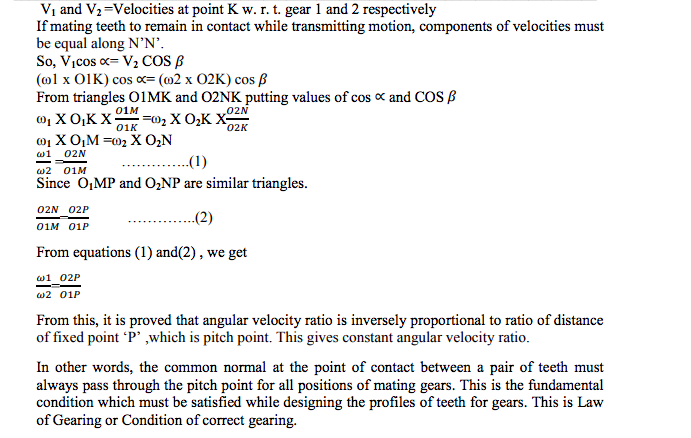
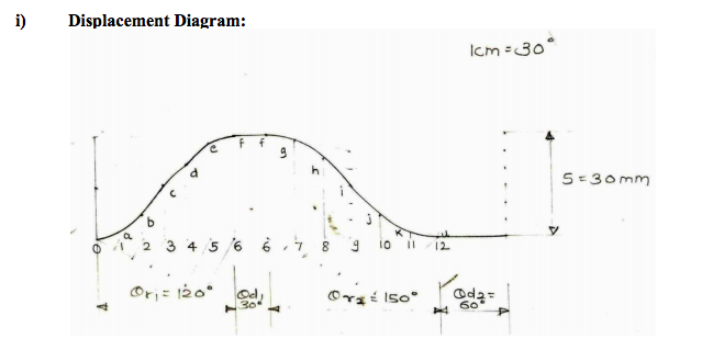
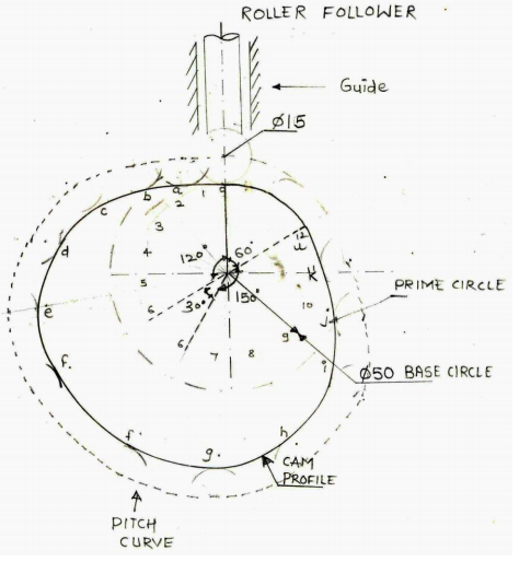
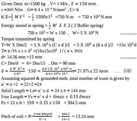
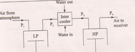
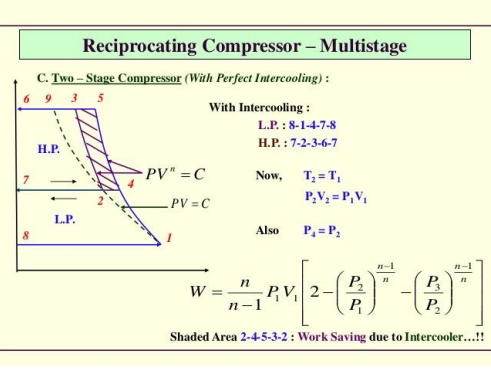
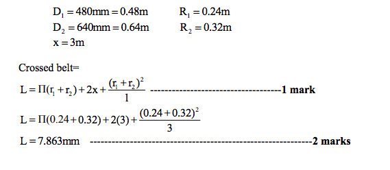
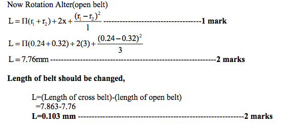
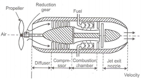
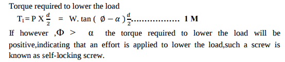
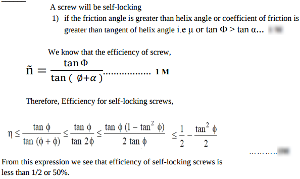
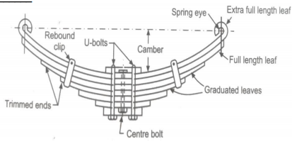
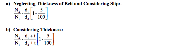
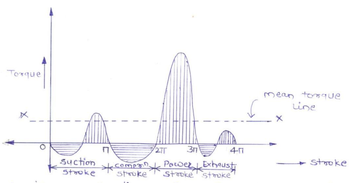
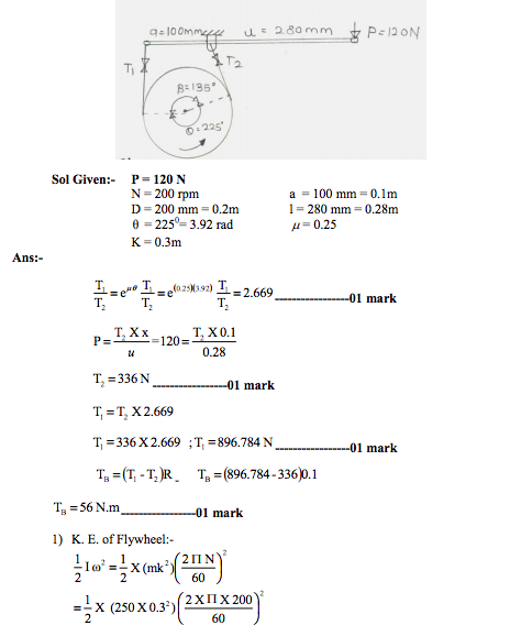
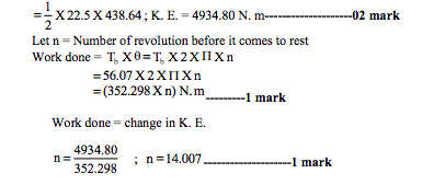
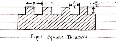
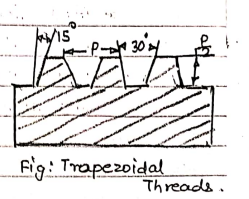
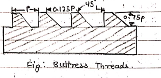
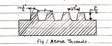
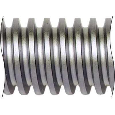
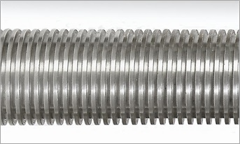
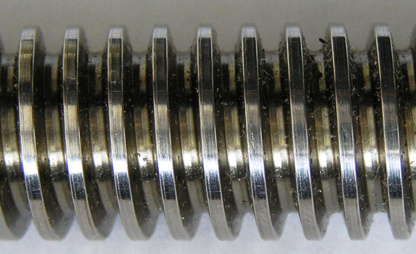
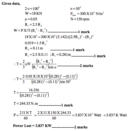
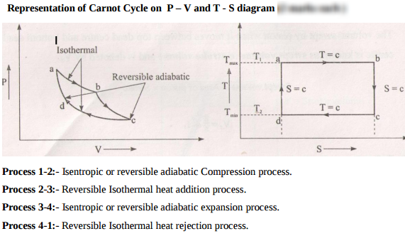

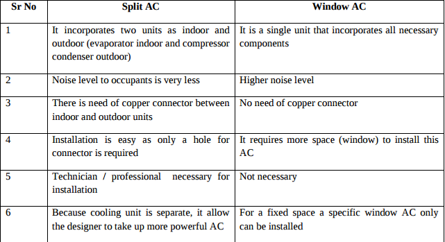
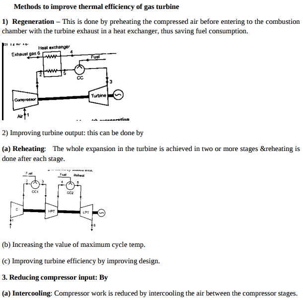 +
+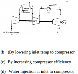
| Que.No | Marks | |
|---|---|---|
| Q ) |
4 |
Question:Explain with neat sketch working of lobe type air compressor.Answer: Lobe type air compressor: it is a rotary type of compressor consisting of two rotors which are driven externally. One rotor is connected to drive and second is connected to gear. These two rotors have two or three lobes having epicycloids, hypocycloid or involutes profiles. In the figure two lobes compressor is shown with a inlet arrangement and receiver. A very small clearance is maintained between surfaces so that wear is prevented. Air leakage through this clearance decreases efficiency of this compressor. During rotation a volume of air V at atmospheric pressure is trapped between left hand rotor and casing . this air is positively displaced with change in volume until space is opened to high pressure region. At this instant some high pressure air rushes back from the receiver and mixed with the blower air until both pressure are equalized .
|
| Q 1a)(a) |
4 |
Question:State four assumptions made for air standard cycle.Answer: Assumption made in air standard cycle Following assumption made in actual cycle to analysis as air standard cycle. 1. The working fluid is perfect gas. 2. There is no change in mass of the working medium. 3. All the process that constitutes the cycle is reversible. 4. Heat is assumed to be supplied from a constant high temperature source and not from chemical reaction during the cycle. 5. There are no heat losses. 6. The working medium has constant specific heats throughout the cycle. ----------------------------------------------------------------------------------------------------- |
| Q 1a)(b) |
4 |
Question:A two stage air compressor with perfect intercooling takes in air at 1 bar pressure and 27 °C. The law of compression in both the stages is Pv1.3 = constant. The compressed air is delivered at 9 bar from the H.P. Cylinder to an air receiver. Calculate per kg. of air i) The minimum work done. ii) The heat rejected to the intercooler.Answer:
|
| Q 1a)(c) |
4 |
Question:Compare SI and CI engine on the basis of i) fuel used, ii) Compression ratio, iii) Weight, iv) Noise and vibrationAnswer: Difference between SI and CI engines
|
| Q 1a)(i) |
4 |
Question:Write any four applications oil hydraulic systemsAnswer: Write any four applications of oil hydraulic systems 1. Earth Moving equipments 2. Broaching machine 3. CNC/VMC/HMC Machines. 4. Hydraulic thread rolling machine 5. Hydraulic press brake. 6. Material handling equipments 7. Hydraulic thread rolling machine 8. Hydraulic cranes ----------------------------------------------------------------------------------------------------- |
| Q 1a)(i) |
2 |
Question:Define Kinematic link with one example.Answer: Kinematic link --Each part of a machine, which moves relative to some other part, is known as a ‘kinematic link (or simply link) or element. Example – any one Example of machine element, (e.g. shaft, spindle, gear, crank, belt, pulley, key etc. ) ----------------------------------------------------------------------------------------------------- |
| Q 1a)(i) |
4 |
Question:What is stress concentration? State its significance in design of machine elementsAnswer: Whenever a machine component changes the shape of its cross section, the simple stress distribution no longer holds good. This irregularity in the stress distribution caused by abrupt changes of form is called as stress concentration
In most machine elements have some forms of discontinuity, namely sudden change in cross section, grooves ,holes, keyways and other changes in sections. these continuity in machine element alter the stress distribution in the neighborhood so that the elementary stress equations no longer described the actual state of stress in the part, such discontinuity is called stress raisers and in the region in which these occur is called the area of stress concentration. Internal cracks and flaws, cavities in welds, blowholes, and pressure in certain points are the common examples of stress raisers. ----------------------------------------------------------------------------------------------------- |
| Q 1a)(ii) |
4 |
Question:What are the effects of contaminants in the oil?Answer: Following are the effects of contaminants in the oil 1) Contaminants in oil make fluid improper or even hazardous for reuse. 2) Excessive heat gets generated during operation of the hydraulic circuit. 3) Electromagnetic radiation contaminated hydraulic system often generates noise thereby polluting the environment. 4) The system operates at lesser efficiency than the desired. ----------------------------------------------------------------------------------------------------- |
| Q 1a)(ii) |
4 |
Question:Write the design procedure of knuckle joint.Answer: Design of Knuckle joint Failure of rod in tension
|
| Q 1a)(ii) |
2 |
Question:Name different mechanisms generated from a single slider crank chain.Answer: Different mechanism generated by single slider crank chain mechanism. a) Reciprocating engine, Reciprocating compressor b) Whitworth quick return mechanism, Rotary engine, c) Slotted crank mechanism, Oscillatory engine d) Hand pump, pendulum pump or Bull engine ----------------------------------------------------------------------------------------------------- |
| Q 1a)(iii) |
4 |
Question:Draw a general layout of pneumatic system and state the function of componentsAnswer:
1) Air inlet filter – Free air from the atmosphere enters the compressor through an air-inlet filter which will essentially keep out the dust and dirt from entering the system. 2) Compressor: It is used to compress the air from atmosphere pressure to the desired higher pressure level. It can be single stage or multistage in operation. 3) Cooler: Removes the heat generated during the process of operation. 4) Pressure switch and control unit: Maintains the pressure in the receiver in the predetermined range by starting and stopping the prime mover. 5) Moisture separator: Cooling air in the cooler results in condensation of vapor in the air. The condensate in the form of water droplets are separated from air. 6) Service unit: Filter – Separates sub-micron level contamination. Regulator – Bring the pressure of air from receiver pressure to the device pressure. Lubricator – Adds lubricants to air. 7) Pipe Line: They carry the compressed air from one location to another. 8) Control Valves: They are required to control the air direction, pressure and flow rate. They are responsible for the smooth and precise control of the pneumatic actuator, and also for the safe operation of the system. 9) Actuator: They will convert the high pressure energy of the compressed air into mechanical force or do useful work. Actuators can either be pneumatic cylinders to provide linear motion or pneumatic motors to provide rotary motion. ----------------------------------------------------------------------------------------------------- |
| Q 1a)(iii) |
2 |
Question:State the advantages of roller follower over knife edge follower.Answer: Advantages of roller follower over knife edge follower a) Roller follower has less wear and tear than knife edge follower. b) Power required for driving the cam is less due to less frictional force between cam and follower. ----------------------------------------------------------------------------------------------------- |
| Q 1a)(iii) |
4 |
Question:Draw a neat sketch of flexible flange coupling and label its main components.Answer:
|
| Q 1a)(iv) |
4 |
Question:Draw the hydraulic circuit showing control of DA cylinder. Using 4 × 2 DC valve. Explain the working in brief.Answer: Draw the hydraulic circuit showing control of DA cylinder using 4 X 2 DC Valve. Explain the working in brief. Fig shows the circuit used to control DA cylinder using 4 X 2 DC Valve. The operation is described as follows: 1) When the 4/2 way DC valve is in its open center position pump oil flows from port P to port A to the blank end of the cylinder, extending the piston rod against a load. The oil in the rodend of the cylinder is free to flow back to the tank via port B and T. 2) When DC valve is activated then it engaged in cross connection of the ports. The cylinder retracts as the oil flows from ports P and B to the rod end. Oil in the blank end is returned to the tank via ports A and T.
|
| Q 1a)(iv) |
2 |
Question:Define slip and creep in case of belt drive.Answer: Slip --- Slip is defined as insufficient frictional grip between pulley (driver/driven) and belt. Slip is the difference between the linear velocities of pulley (driver/driven) and belt. Creep ----- Uneven extensions and contractions of the belt when it passes from tight side to slack side. There is relative motion between belt and pulley surface, this phenomenon is called creep of belt. ----------------------------------------------------------------------------------------------------- |
| Q 1a)(iv) |
4 |
Question:Draw neat labeled sketches of Acme and square thread profile and state its relative characteristics.Answer:
Characteristics of Acme thread : (i)thread angle is 290 (ii) permit the use of split nut (iii)easy to manufacture (iv) max. bursting pressure on the thread Characteristics of Square thread : (i) zero profile thread angle (ii) minimum bursting pressure on the nut ----------------------------------------------------------------------------------------------------- |
| Q 1a)(v) |
2 |
Question:Give four advantages of chain drive over belt drive.Answer: Advantages of chain drive over belt drive a) No slip takes place in chain drive as in belt drive there is slip. b) Occupy less space as compare to belt drive. c) High transmission efficiency. d) More power transmission than belts drive. e) Operated at adverse temperature and atmospheric conditions. f) Higher velocity ratio. g) Used for both long as well as short distances ----------------------------------------------------------------------------------------------------- |
| Q 1a)(vi) |
2 |
Question:State the effect of centrifugal tension on power transmission.Answer: Effect of centrifugal tension on power transmission: As the belt passes over the pulley with high velocity, centrifugal force is produced on the belt, which tends to act on the belt. This force tries to move the belt away from the pulley. This force is given by, TC = m x V2 There is no effect of centrifugal tension on power transmitted. ----------------------------------------------------------------------------------------------------- |
| Q 1a)(vii) |
2 |
Question:Define fluctuation of energy and coefficient of fluctuation of energy.Answer: a) Fluctuation of energy -- The difference of maximum and minimum kinetic energy of flywheel is known as Fluctuation of energy b) Coefficient of fluctuation of energy -- - It is defined as the ratio of the maximum fluctuation of energy to the work done per cycle. It is denoted by ke = (E1 - E2)/work done per cycle ----------------------------------------------------------------------------------------------------- |
| Q 1a)(viii) |
2 |
Question:State the adverse effect of imbalance of rotating elements of machine.Answer: Adverse effect of imbalance of rotating elements: a) Vibration, noise and discomfort, b) Machine accuracy get disturbed, c) Power losses, d) More maintenance ----------------------------------------------------------------------------------------------------- |
| Q 1b)(a) |
6 |
Question:A four cylinder engine running at 1200 rpm delivers 20 kW. The average torque when one cylinder was cut is 110 N.m. Find the indicated thermal efficiency if the calorific value of the fuel is 43 MJ/Kg and the engine uses 360 gm. of gasoline (fuel) per kW. hr.Answer:
|
| Q 1b)(b) |
6 |
Question:Explain with neat sketch working of non dispersive infra red (NDIR) gas analyser.Answer: Non dispersive infra red gas analyzer ( NDIR) : The working principle of infra red gas exhaust gas analyzer is as shown in figure . It works on the principle of hetero atomic gases absorbs infra red energy at distinct and separated wavelength. The absorbed energy raises the temperature and pressure of confined gas. This enables to measure contents of hydro carbon and carbon monoxide. This is a faster method of gas analysis. The standard sample is filled in reference cell R . the sample of gas under testing is filled in cell S . The detector cell D is filled with specific gas to be measured, say CO2 . the detector cell is divided into two compartments by diaphragm. It is very sensitive. Initially infra red energy in both compartment is same and indicator reading is zero. The sample is connected to exhaust gas. This lowers pressure on sample side. It will absorb energy in proportion to concentration of CO2 in sample and detector gives percentage of CO2 present in the samp0le.
|
| Q 1b)(i) |
4 |
Question:State any four inversions of single slider crane chain. Describe any one with neat sketch.Answer: 1.Reciprocating engine, Reciprocating compressor; 2. Whitworth quick return mechanism, Rotary engine, 3.Slotted crank mechanism, Oscillatory engine. 4.Hand pump, pendulum pump. 1.Reciprocating engine, Reciprocating compressor link 1 is fixed
2.Whitworth quick return mechanism, Rotary engine link 2 is fixed,
3.- Oscillatory engine. Slotted crank mechanism. link 3 is fixed
4. Hand pump, pendulum pump. link 4 is fixed
----------------------------------------------------------------------------------------------------- |
| Q 1b)(i) |
6 |
Question:Draw actual hydraulic system and explain its working.Answer: Draw actual hydraulic system and explain its working. Oil hydraulics system uses pressurized oil which is circulated through various components of the hydraulic system to perform the given task. The various components of hydraulic system have to perform its intended function and they are arranged to form a layout of the system as per sequence of operation of hydraulic system. This arrangement of various hydraulic system components as per the nature of equipment/machine is known as actual layout of the system. The oil from reservoir is cleaned by the filter and sucked by the pump when driven by the motor. The pump increases the pressure of oil and high pressure oil is then passed through relief valve to drain excess pressure. Now oil is circulated to the direction to control to the actuator. The oil moves the piston and piston rod to give output force/motion. This motion/force is then utilized for performing the work/task. The oil from the relief valve and outlet of the actuator transferred to the reservoir through drain line and recirculated in the hydraulic system
|
| Q 1b)(i) |
6 |
Question:State and explain main considerations in machine design.Answer: Main considerations in machine design Type of loads and stresses caused by the load: the load on a machine component, may act in several ways, due to which, the internal stresses are set up. Mechanism: the successful operation of any machine depends largely upon the simplest arrangement of the parts, which will give desired motion Selection of material: designer should know the deep knowledge of properties of materials and behavior under working conditions Convenient and economical features: the designed machine must be convenient to operate and cost wise economical for the customer Use of standard part: reduced the overall cost Safety of operation: to avoid accidental hazards, care should be taken by designer Workshop facilities: a designer should be familiar with the limitations of his employer’s workshop, in order to avoid necessity of vendors Number of machines to be manufactured Cost of construction and assembly: designed machine should be cheap and easy to assem6ble Frictional resistance and lubrication: designer should provide necessary lubrication to the parts, where there is a sliding, rolling and rotating motion ----------------------------------------------------------------------------------------------------- |
| Q 1b)(ii) |
4 |
Question:Compare multiplate clutch with cone clutch on the following basis. (1) Power Transmission (2) SizeAnswer: Comparison of multiplate clutch and Cone clutch:
|
| Q 1b)(ii) |
6 |
Question:Explain with neat sketch the working of rotary spool type DC valve.Answer: A rotary spool valve consists of a rotating spool which aligns with ports in stationary valve casing, so that fluid is directed to required port. A/B/P/R are the ports in casing. The port ‘P’ is a pressure port though which pressurized oil is coming in the valve. ‘R’ port is the port through which used oil is returning to oil tank. From fig port p is connected to port B and port A is connected to port R
|
| Q 1b)(ii) |
6 |
Question:A hollow shaft is required to transmit 50 kW power at 600 rpm. Calculate its inside and outside diameters if its ratio is 0.8. Consider yield strength of material as 380N/mm2 and factor of safety as 4.Answer: Given : P= 50 KW = 50000W Speed = 600rpm k=Di/do = 0.8 σyt= 380 N/mm2 Factor of safety= 4 Design stress σt=σyt/fos =380/4 =95 Shear stress = τ =σt/2 = 95/2 =47.5N/mm2 Torque transmitted by hollow shaft T = P x 60/2πN T = 50000 x 60/2π x600 T = 795.67 N-m T= 795670 Nmm T= π/16 Xτ X do3 (1-k 4 ) 795670 =π/16 X 47.5 X do3 ( 1-0.84 ) Do3=144529.313 Do = 53 mm say 55 mm Di = 0.8X 55 = 44mm ----------------------------------------------------------------------------------------------------- |
| Q 1b)(iii) |
4 |
Question:The central distance two shaft is 4m having two pulleys with diameter having 500mm and 700mm respectively find the length of belt required - (1) for open belt drive (2) for cross belt driveAnswer:
|
| Q 2 a ) |
8 |
Question:Explain with the help of neat sketches three basic types of lever. State one application of each type.Answer: In the first type of levers, the fulcrum is in between the load and effort. In this case, the effort arm is greater than load arm, therefore M.A. obtained is more than 1 Application: Bell crank levers used in railway signaling arrangement, rocker arm in I.C. Engines , handle of a hand pump, hand wheel of a punching press, beam of a balance, foot lever (any 1) In the second type of levers, the load is in between the fulcrum and effort. In this case, the effort arm is more than the load arm, therefore M.A. is more than 1. Application: levers of loaded safety valves, wheel barrow, nut cracker (any1) In the third type of levers, the effort is in between the fulcrum and load. Since the effort arm, in this case, is less than the load arm, therefore M.A. is less than 1 Application: a pair of tongs, the treadle of sewing machine
|
| Q 2 a ) |
4 |
Question:Explain a scotch yoke mechanism with a neat sketch.Answer:
|
| Q 2 a ) |
8 |
Question:Differentiate vapour compression and vapour absorption refrigeration system. (min. eight points of difference)Answer: Differences between Vapour Absorption and Vapour Compression refrigeration system
|