Q.1. Explain with sketch Regenerative circuit.

![]()
Ans : A circuit is said to be operating on re-generative principle when the fluid returning from other end of cylinder is forced into the head end of cylinder. Obviously, some energy is consumed to force out the fluid from piston-rod end when cylinder is extending. The re-generative circuit enables to utilize this part of energy, which would have otherwise wasted. The net result of re-generation is increase in cylinder speed, with same discharge of pump.The circuit in fig. depicts a typical re-generative circuit with solenoid operated 4/3 directional control valve. The circuit is similar to the previous linear circuit except
the change in center position of direction control

![]()
When the valve is in central position the cylinder extends, with about twice the normal speed, thus effecting the re-generative function. When the valve shifts to right position, the regenerative effect is nullified and cylinder moves with normal speed (as decided by pump flow).When the valve shifts to left, the
cylinder retracts. The regenerative principle can be applied to any motion i.e. extending or retracting.
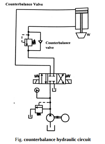
Q.2. Explain with sketch Counter balance Hydraulic circuit .
Ans : Counterbalance valves are commonly used to counterbalance a weight or external force or counteract a weight such as a platen or a press and keep it from freefalling.Figure1.16 illustrates the use of a counterbalanceor back-pressure valve to keep a vertically mounted cylinder in the upward position while the pump idles, that is, when the DCV is in its center position. During the downward movement of the cylinder, the counterbalance valve is set to open at slightly above the pressure required to hold the piston up (a check valve does not permit flow in this direction). The control signal for the counterbalance valve can be obtained from the blank end or rod end of the cylinder. If derived from the rod end, the pressure setting of the counterbalance valve equals the ratio of the load to the annulus area of the piston. If derived from the blank end, the pressure etting equals the ratio of load to the area of piston. This pressure is less and hence usually it has to be derived from the blank end. This permits the cylinder to be forced downward when pressure is applied on the top. The check valve is used to lift the cylinder up as the counterbalance valve is closed in this direction. The directional control valve unloads the pump
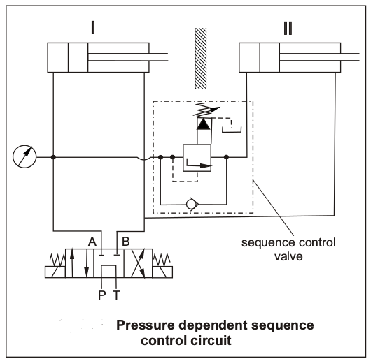
Q.3. Explain with sketch Sequencing circuit .
As the name suggests the sequencing ciruit is used when two or more operations are to be sequenced one after another, means the second operation should not start until the first operation is not completed. This is needed in lot of applications like automation and processing.The sequencing circuits can be travel dependent or pressure dependent, means the next circuit gets oil when either the first circuit completes the travel or the pressure builds above certain level. Following circuit is Pressure dependent sequencing circuit
As shown in th diagram the first cylinder is operated first, when the piston of first cylinder reaches its end point, the pressure starts building, when the pressure builds to the set point of sequence control valve, the valve opens and the oil is supplied to the next cylinder.
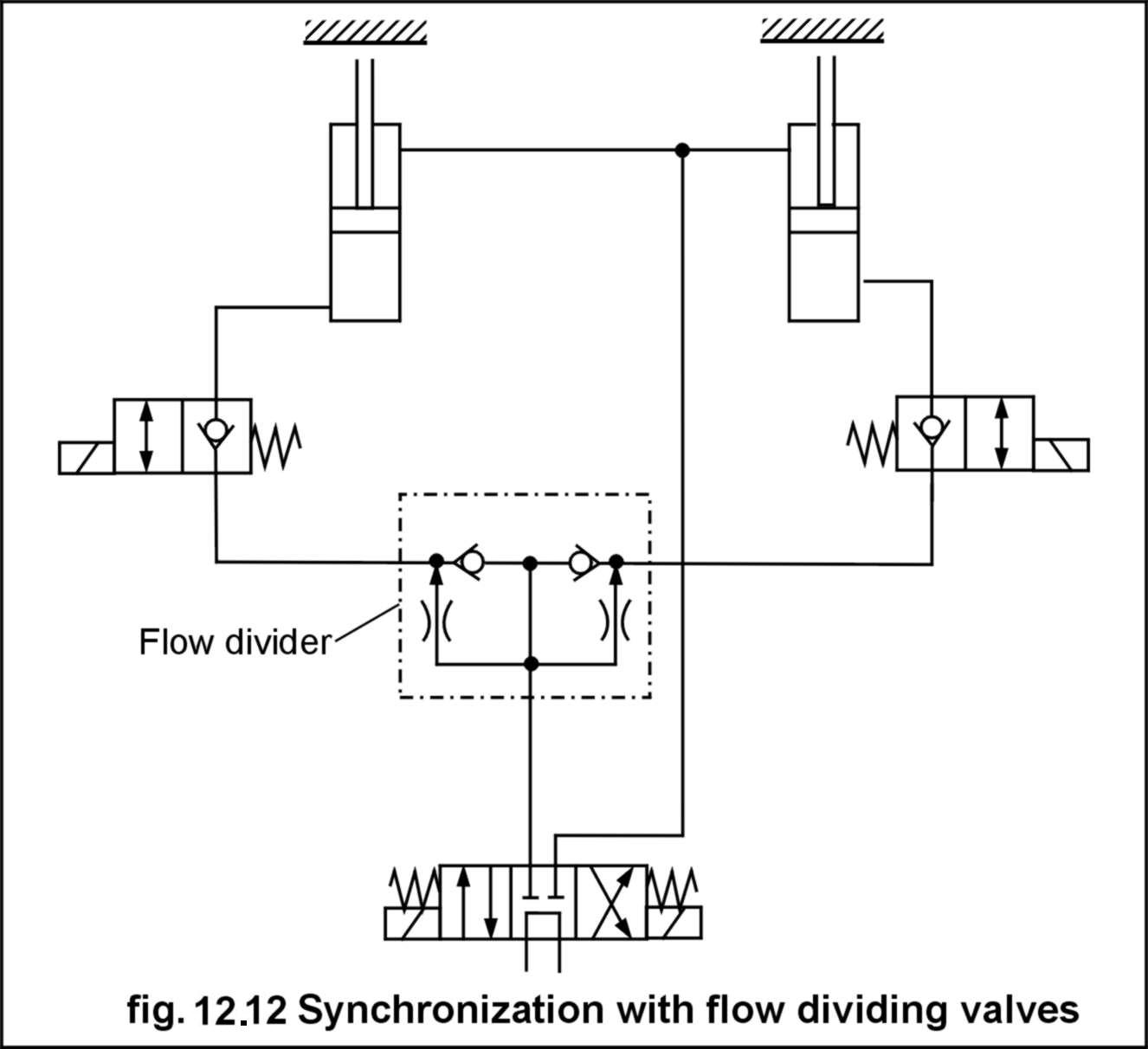
Q.4. Explain with sketch Synchronizing circuit .
A synchronizing circuit is used when we need the synchronized movement of two or more cylinders(or motors). Means we need that the both cylinders move exactly at same time and
at same speed. This is required in several applications. Synchronization can be achieved by mechanical means of coupling also. The following diagram depicts the synchronizing circuit
with the use of flow dividers. Flow dividing valves can be used effectively to obtain the synchronized motion. As shown in fig below flow dividing valves divide the flow into two equal parts
irrespective of load. One point should noted that flow dividing valve synchronize extension stroke only (in case of circuit diagram shown),if synchronization is required in the return stroke also, then additional flow divider in top line must be installed.
`
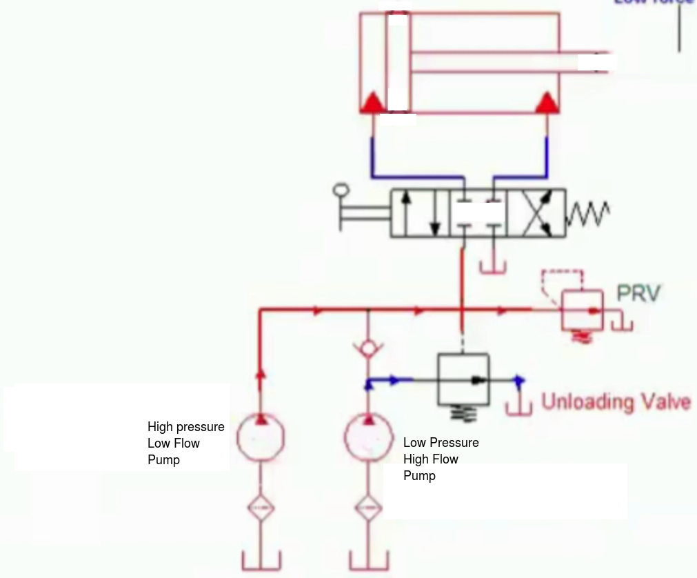
Q.5. Explain with sketch two pump unloading circuit .
A two pump unloading circuit is used in situation where some part of the piston travel is required at high speed and low pressure and some small part is required at High pressure and low speed. For such purpose it is uneconomical to use a very high pressure and high volume pump. Instead the unloading circuit is used which uses two pumps for two purposes. When the motion is required with less force(pressure) both of the pumps discharge in the cylinder, and when the motion is required with high force(pressure) only the high pressure pump discharges to the cylinder and low pressure pump returns back oil to tank through unloading valve. Application: This circuit finds application in machine tools like punching machine and other cutting machines.
- Log in to post comments