fsd
stress is load per unit area.
- Log in to post comments
stress is load per unit area.
Data: Initial tension, To = 2000 N, coefficient of friction, µ = 0.3, Angle of lap, θ = 1500 = 1500 x П / 180 = 2.618 rad, Smaller pulley radius, R = 200 mm, hence, D = 400 mm, Speed of smaller pulley, N = 500 r.p.m. We know that the velocity of the belt, v = П = П = 10.47 m/sec (01 mark) Let T1 = Tension in the belt on the tight side, N Let T2 = Tension in the belt on the slack side, N We know that, T0 = Hence, 2000 = (T1 + T2) / 2 Thus, (T1 + T2) = 4000 N ....................... (1) We also know that, = therefore, = or = 2.2 .............
Roller follower is preferred over knife edge follower Knife-edge of the follower will cause the wear of the cam. Higher load on the small contact area the follower likely to cause wear at the tip of Knifeedge due to more stresses. Knife-edge follower practically not feasible for higher torque / load applications. More friction due to sliding motion of the knife-edge follower and hence, more maintenance. Roller follower on the other hand produces smooth operation with less wear and tear of both cam and follower.
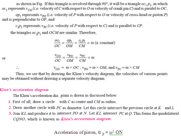
Let OC be the crank and PC the connecting rod of a reciprocating steam engine, as shown in Fig. Let the crank makes an angle θ with the line of stroke PO and rotates with uniform angular velocity ω rad/s in a clockwise direction. The Klien’s velocity and acceleration diagrams are drawn as discussed below:
Crank and slotted lever quick return motion mechanism. This mechanism is mostly used in shaping machines, slotting machines and in rotary internal combustion engines. In this mechanism, the link AC (i.e. link 3) forming the turning pair is fixed, as shown in fig. The link 3 corresponds to the connecting rod of a reciprocating steam engine. The driving crank CB revolves with uniform angular speed about the fixed centre C. A sliding block attached to the crank pin at B slides along the slotted bar AP and thus causes AP to oscillate about the pivoted point A.
Sl. No
Machine
Structure
1
All parts / links have relative motion
No relative motion between the links
2
It transforms the available energy into some useful work
No energy transformations
3
The kinematic link of a machine may transmit both power and motion
The member of the structure transmit forces only
4
Examples: I.C. Engine, Machine tools, steam engine, type writer, etc.
Example: Truss of roof, frame of machine, truss of bridge
V- Belt drive – air compressor, machine tools (drilling machine) Flat belt drive - lathe headstock, floor mill, stone crusher unit Gear drive – gear box of vehicles, cement mixing unit, machine tools, I.C. Engine, differential of automobile, dial indicator Chain drive – Bicycle, cranes, Hoists, bikes
(Types of clutches: Two marks, applications Two marks) Types of clutches: a) Single plate clutch b) Multi plate clutch c) Cone clutch d) Centrifugal clutch Applications: a) Single plate clutch: Heavy vehicles, four-wheeler such as car, truck, bus b) Multi plate clutch: Two wheelers, mopeds, scooters, bikes c) Cone clutch: Machine tools, automobiles, press work d) Centrifugal clutch: mopeds, Luna
The process of providing the second mass in order to counter act the effect of the centrifugal force of the disturbing mass is called balancing. In order to prevent the bad effect of centrifugal force of disturbing mass, another mass (balancing) is attached to the opposite side of the shaft at such a position, so as to balance the effect of centrifugal force of disturbing mass. This is done in such a way that the centrifugal forces of both the masses are made equal and opposite.