State four applications of flywheel.
Applications of flywheel : Used in Internal combustion engines, press machines, mills, punching machines.
Applications of flywheel : Used in Internal combustion engines, press machines, mills, punching machines.
The function of a governor is to regulate the mean speed of an engine, when there are variations in the load e.g. when the load on an engine increases, its speed decreases, therefore it becomes necessary to increase the supply of working fluid. On the other hand, when the load on the engine decreases, its speed increases and thus less working fluid is required. The governor automatically controls the supply of working fluid to the engine with the varying load conditions and keeps the mean speed within certain limits.
Conditions for ‘V’ Belt drive selection :
1. Great amount of Power to be transmitted,
2. Requirement of the high velocity ratio (maximum 10).
3. Small Centre distance between the shafts
4. Positive drive requirement
5. Compact Space
Slip of belt : The motion of belts and shafts assuming a firm frictional grip between the belts and the shafts. But sometimes, the frictional grip becomes insufficient. This may cause some forward motion of the driver without carrying the belt with it. This may also cause some forward motion of the belt without carrying the driven pulley with it. This is called slip of the belt and is generally expressed as a percentage.
Motion of the Follower :
1. Uniform velocity, 2. Simple harmonic motion,
3. Uniform acceleration and retardation, and 4. Cycloidal motion.
Each part of a machine, which moves relative to some other part, is known as a kinematic link.
When the kinematic pairs are coupled in such a way that the last link is joined to the first link to transmit definite motion (i.e. completely or successfully constrained motion), it is called a kinematic chain.
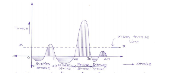
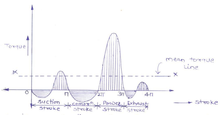
A turning moment diagram for a four stroke cycle internal combustion engine, we know that in a four stroke cycle internal combustion engine, there is one working stroke after a crank has turned through two revolution i.e.7200 . Since the pressure inside the engine cylinder is less than the atmospheric pressure during suction stroke therefore a negative loop is formed. During the compression stroke, the work is done on gases, therefore a higher negative loop is obtained.
A simple band brake drum:
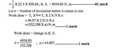
A turning moment diagram for a four stroke cycle internal combustion engine, we know that in a four stroke cycle internal combustion engine, there is one working stroke after a crank has turned through two revolution i.e.7200 . Since the pressure inside the engine cylinder is less than the atmospheric pressure during suction stroke therefore a negative loop is formed. During the compression stroke, the work is done on gases, therefore a higher negative loop is obtained.