You are here

3

Draw the hydraulic circuit showing control of DA cylinder...

Draw the hydraulic circuit showing control of DA cylinder using 4 X 2 DC Valve. Explain the working in brief. Fig shows the circuit used to control DA cylinder using 4 X 2 DC Valve. The operation is described as follows: 1) When the 4/2 way DC valve is in its open center position pump oil flows from port P to port A to the blank end of the cylinder, extending the piston rod against a load. The oil in the rodend of the cylinder is free to flow back to the tank via port B and T. 2) When DC valve is activated then it engaged in cross connection of the ports.

Explain working of counterbalance hydraulic circuit with neat diagram........

Counterbalance valves are commonly used to counterbalance a weight or external force or counteract a weight such as a platen or a press and keep it from freefalling.Figure1.16 illustrates  the use of a counterbalance or back-pressure valve to keep a vertically mounted cylinder in the upward position while the pump idles, that is, when the DCV is in its center position. During the downward movement of the cylinder, the counterbalance valve is set to open at slightly above the pressure required to hold the piston up (a check valve does not permit flow in this direction).

Explain with neat sketch the working of meter out hydraulic circuit...........

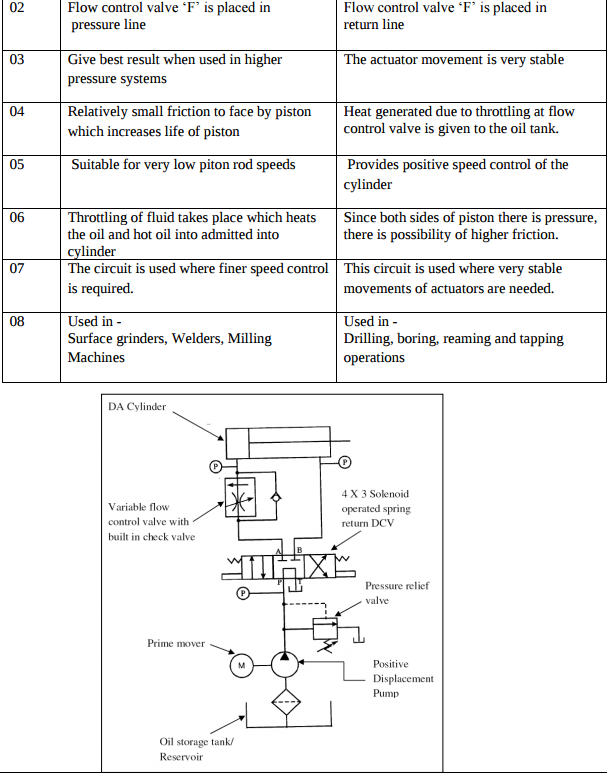
Meter OUT Circuit A typical meter out circuit is shown in figure. Here the flow control valve is installed in the return line metering the fluid being discharged. In that way, this circuit also gives the control over the actuating speed. But this way of control offers altogether different characteristics to the circuit. Now, the circuit pressure has to overcome the load resistance and the pressure drop across the flow control valve. However, as the flow control valve is on the right side of the piston, the differential area will cause rise in the pressure.

Explain the working of counter balance valve in hydraulic circuit..........

Counter Balance Valve It is basically a relief valve but it is used to set up a back pressure in a circuit to prevent load from falling. They are frequently employed in vertical presses, loaders, lift trucks and other machines that must maintain a particular position or hold a suspended load. In such applications, the counterbalance valve creates a back pressure to prevent the movement of piston rod of cylinder

Explain with neat sketch the working of hydraulic circuit for milling machine. ...........

Working of hydraulic circuit for milling machine. Hydraulic circuit for milling machine is comparatively different from other circuits. Table movement of milling machine is required to be adjustable for different feeds for different type of work. Therefore for both strokes of the cylinder, on both ends of cylinder flow control valves are used. Another feature of this circuit is that there are two pumps 1. Main pump – low pressure high discharge 2.

State the different modes of failure of gear teeth and their possible remedies to avoid the failure.

1. Bending failure. 2. Pitting. 3. Scoring. 4. Abrasive wear. 5. Corrosive wear Remedies to avoid failure: 1. Bending failure. In order to avoid such failure, the module and face width of the gear is adjusted so that the beam strength is greater than the dynamic load. 2. Pitting. In order to avoid the pitting, the dynamic load between the gear tooth should be less than the wear strength of the gear tooth. 3. Scoring.

State the effect of keyway on the strength of the shaft.............

The keyway is a slot machined either on the shaft or in hub to accommodate the key. It is cut by vertical or horizontal milling cutter. A little consideration will show that the keyway cut into the shaft reduces the load carrying capacity of the shaft. This is due to the stress concentration near the corners of the keyway and reduction in the crosssectional area of the shaft. It other words, the torsional strength of the shaft is reduced. The following relation for the weakening effect of the keyway is based on the experimental results by H.F. Moore.

How keys are classified? Give detailed classification of keys with neat sketches; also state their applications.

Keys are classified on the basis of shape and application of keys.………………are 1) Sunk Key : a) Rectangular sunk key b) square sunk key c) Gib head key d) feather key e) Woodruff key 2) Saddle key a) Flat saddle key b) hollow saddle key 3) Round key 4) Splines …………………: 1) Sunk Key : used for heavy duty application a) Rectangular sunk key : for preventing rotation of gears and pulleys on shaft b) Gib headed key: used where key to be removed frequently.

Pages

Subscribe to RSS - 3