2017 WINTER
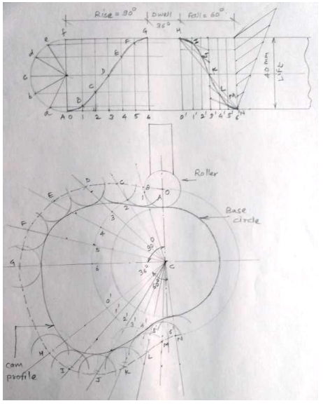
Draw the profile of a cam to raise a valve with S.H.M. through 40 mm in of revolution, keep it fully raised through 1/10 th 1 th 4 revolution and to lower it with uniform acceleration and retardation in 1/6 th revolution. The valve remains closed during t
Fig shows a displacement diagram and a cam profile for the roller follower.
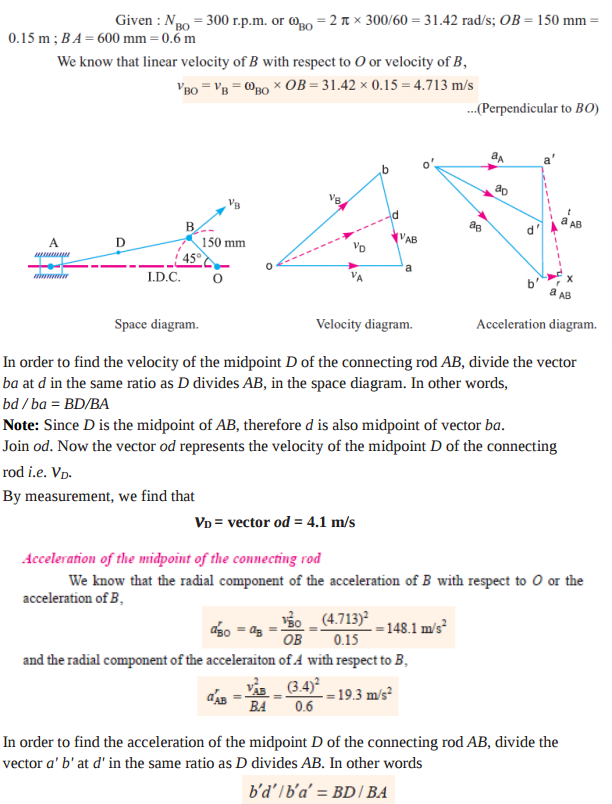
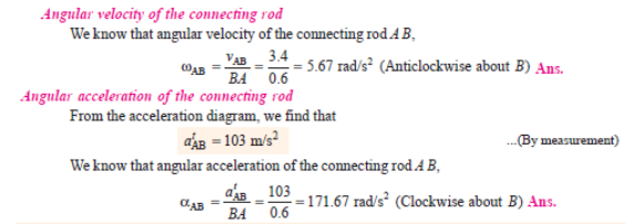
The crank of a slider crank mechanism rotates clockwise at a constant speed of 300 rpm. The crank is 150 mm and the connecting rod is 600 mm long. Determine : (i) linear velocity and acceleration of the mid-point of the connecting rod, and (ii) angular ve
Note: Since D is the midpoint of AB, therefore d' is also midpoint of vector b' a'. Join o' d'. The vector o' d' represents the acceleration of midpoint D of the connecting rod i.e. aD.
By measurement, we find that aD = vector o' d' = 117 m/s2
Given: Lift = 40 mm Rise = ¼ x 360 = 900 Fall =1/6 x 360 = 600 Dwell = 1/10 x 360 =360
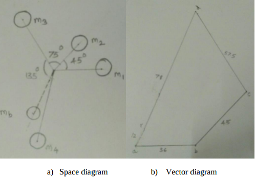
Four masses attached to a shaft and their respective radii of rotation are given as : m 1 = 180 kg m 2 = 300 kg m 3 = 230 kg m 4 = 260 kg r 1 = 0.2 m r 2 = 0.15 m r 3 = 0.25 m r 4 = 0.3 m The angles between successive masses are 45, 75 and 135. Find th
Given : m1 = 180 kg, m2 = 300 kg, m3 = 230 kg, m4 = 260 kg r1 = 0.2 m, r2 = 0.15 m, r3 = 0.25 m, r4 = 0.3 m ϴ1 = 45, ϴ2 = 75, ϴ = 135 The centrifugal forces are given by - m1r1 = 36, m2r2 = 45, m3r3 = 57.5, m4r4 = 78
From vector diagram the resultant force is at 60 to the mass m1 and is represented by ar ar = 12 kg m Therefore mb * rb = 12 kgm Balancing mass mb = 12/0.2 = 60 kg at an angle of 2400 with the direction of m1 mass
A flat foot step bearing 225 mm in diameter supports a load of 7500 N. If the co-efficient of friction is 0.09 and the shaft rotates at 600 rpm, calculate the power lost in friction.
Problem on Foot step bearing D = 225 mm = 0.225 m W = 7500 N µ = 0.09 N = 600 rpm ω = 2 π N / 60 =62.83 rad/sec Uniform pressure condition Frictional torque T = 2/3 µ W R = 50.625 Nm Power lost in friction = T x ω = 50.625 x 62.83 = 3180.8 W --------Ans Uniform wear condition Frictional torque T = 1/2 µ W R = 37.98 Nm Power lost in friction = T x ω = 37.98 x 62.83 = 2385.57 W -------- Ans
Explain with neat sketch construction and working of eddy current dynamometer.
Eddy Current Dynamometer : It consists of a stator on which are fitted a number of electromagnets and a rotor disc made of copper or steel and coupled to the output shaft of the engine. When the rotor rotates, eddy currents are produced in the stator due to magnetic flux set up by the passage of field current in the electromagnets. These eddy currents oppose the motion of the rotor thus loading the engine. The eddy currents are dissipated in producing heat so that this type of dynamometer also requires some cooling arrangements.
Compare flywheel and governor.
Justify that slider crank mechanism is a modification of the basic four bar mechanism with neat sketch.
Justification for a single slider crank mechanism is a modification of four bar chain mechanism is as given below. 1) Single slider mechanism has four kinematic links – crank, connecting rod, frame and slider and four bar mechanism has crank, coupler, frame and a follower. 2) A follower in four bar mechanism is replaced by a slider. 3) A four bar mechanism has 4 turning pairs and single slider crank mechanism has also four pairs, but one of the turning pairs is replaced by a sliding pairs.
State advantages and disadvantages of chain drive over belt drive
Advantages of chain drive over belt drive (Any four)
a) No slip takes place in chain drive as in belt drive there is slip.
b) Occupy less space as compare to belt drive.
c) High transmission efficiency.
d) More power transmission than belts drive.
e) Operated at adverse temperature and atmospheric conditions.
f) Higher velocity ratio.
g) Used for both long as well as short distances.
Disadvantages of chain drive: 1. Manufacturing cost of chains is relatively high
Give detailed classification of followers.
Types of followers The followers may be classified as discussed below: