List any four applications of pneumatic rotary actuator...........
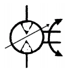
In all pneumatic power tools like screw drivers, angle grinders, straight grinders. To rotate conveyor belts in food industry. Power device in printing press machine Agitators and mixers Vibrators. symbol for variable speed bidirectional air motor