You are here

17608

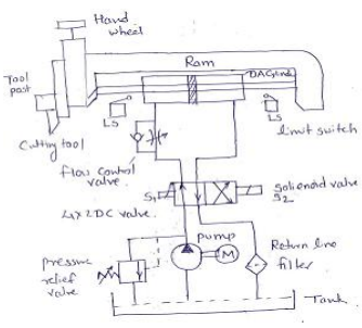
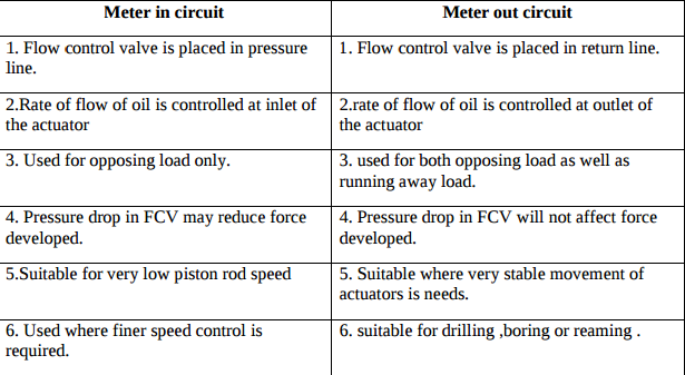
How can the speed control of any actuator be achieved........

Speed control of any actuator (Cylinders or motors) can be controlled using flow control valves. Varying the rate of flow of oil will vary the speed of the actuator.(Explanation 1Mark)  In meter in circuit, rate of flow of oil is controlled at inlet of the actuator.  In meter out circuit, rate of flow of oil is controlled at outlet of the actuator.  In bleed off circuit, rate of flow of oil is controlled in the by-pass line leading towards the tank.

In cold climate why oil tank is equipped with oil heaters? Explain.

Oil heaters:  When hydraulic circuit works in cold climate, then oil is solidifies below 5 o C temperature.  To liquefy the oil electrical heater or thermostatic heater are equipped with oil tank.  This increase the operating and maintenance cost of hydraulic system  The cost of hydraulic system is higher.  It heats the oil so that its viscosity increases and it can flow in the system smoothly.  Thermostatically controlled oil heater commonly used

Explain working of directly operated.........

When oil under pressure is supplied to port A, the oil exerts pressure on the ball against the spring force, hence the ball will be lifted off from its seat and creates a passage for


oil to flow. Hence oil can flow from port A to port B. when under pressure is supplied in opposite direction that is to port B, the oil force the ball to sit firmly in its seat, hence the passage is closed by ball. The oil cannot flow port B to port A.

Explain construction and working of gear pump.

It consists of a pump housing in which a pair of precisely machined meshing gears runs with minimal radial and axial clearance as shown in fig. One of the gears, called a driver, is driven by a prime mover. The driver drives another gear called a follower. As the teeth of the two gears separate, the fluid from the pump inlet gets trapped between the rotating gear cavities and pump housing. The trapped fluid is then carried around the periphery of the pump casing and delivered to outlet port.

What is impulse circuit? Explain

the main valve using the impulse of an impulse valve. As shown in fig. in circuit has two valves ; main valve and impulse valve. Main valve is a single pilot operated spring return type 4/2 direction control valve. Impulse valve is palm button operated spring return type 3/2 direction control valve. In normal position of valves, the double acting cylinder is in retracted position. When the palm button of impulsive valve is pressed manually, compressed air flows to the pilot port of main valve. Hence the speed of main valve will be shifted to the second position.

Pages

Subscribe to RSS - 17608