You are here

17608

Explain the construction and working of doubled acting reciprocating compressor with neat sketch.

Double acting reciprocating air compressor is similar to double acting reciprocating pump. It is comprised of following parts: 1) Cylinder 2) Piston and piston rod and connecting rod. 3) Crank and crank case 4) Two suction valves and two delivery valves. 5) One inlet port and one outlet port It uses four bar mechanism. There are 4 valves (2 suction valves and 2 delivery valves) shown at A, B, C, D in figure. There are cooling fans similar to single acting compressors. The crank rotates on electric motor/engine/turbine.

Why pressure relief valve is used in hydraulic circuit............

Pressure Relief Valve used because; 1. To Maintain desired pressure levels in the circuit. 2. To set maximum pressure in hydraulic system. 3. Protect the pump and other system components from overloading. 4. It acts as a relief and safety device ExplanationSimple pressure relief valve is also a Direct operated pressure relief valve. It consists of Poppet, spring, pressure setting knob and valve body.

What is swash plate? What is its use........

It’s an inclined plate in axial piston pump on which all pistons are connected through piston rod. This swash plate is usually inclined. Use – It is helps to reciprocate the piston of axial piston pump while the cylinder block is rotating Working: Motor drives the shaft, which in turn rotates the entire cylinder block. The pistons are connected to inclined swash plate through piston rod. Now since swash plate is inclined and block is rotating, the piston reciprocates inside the barrel.

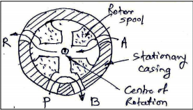
Explain with neat sketch the working of rotary spool type DC valve.

A rotary spool valve consists of a rotating spool which aligns with ports in stationary valve casing, so that fluid is directed to required port. A/B/P/R are the ports in casing. The port ‘P’ is a pressure port though which pressurized oil is coming in the valve. ‘R’ port is the port through which used oil is returning to oil tank. From fig port p is connected to port B and port A is connected to port R


Draw actual hydraulic system and explain its working.

Draw actual hydraulic system and explain its working. Oil hydraulics system uses pressurized oil which is circulated through various components of the hydraulic system to perform the given task. The various components of hydraulic system have to perform its intended function and they are arranged to form a layout of the system as per sequence of operation of hydraulic system. This arrangement of various hydraulic system components as per the nature of equipment/machine is known as actual layout of the system.

Draw the hydraulic circuit showing control of DA cylinder...

Draw the hydraulic circuit showing control of DA cylinder using 4 X 2 DC Valve. Explain the working in brief. Fig shows the circuit used to control DA cylinder using 4 X 2 DC Valve. The operation is described as follows: 1) When the 4/2 way DC valve is in its open center position pump oil flows from port P to port A to the blank end of the cylinder, extending the piston rod against a load. The oil in the rodend of the cylinder is free to flow back to the tank via port B and T. 2) When DC valve is activated then it engaged in cross connection of the ports.

What are the effects of contaminants in the oil?

Following are the effects of contaminants in the oil 1) Contaminants in oil make fluid improper or even hazardous for reuse. 2) Excessive heat gets generated during operation of the hydraulic circuit. 3) Electromagnetic radiation contaminated hydraulic system often generates noise thereby polluting the environment. 4) The system operates at lesser efficiency than the desired.

Write any four applications oil hydraulic systems

Write any four applications of oil hydraulic systems 1. Earth Moving equipments 2. Broaching machine 3. CNC/VMC/HMC Machines. 4. Hydraulic thread rolling machine 5. Hydraulic press brake. 6. Material handling equipments 7. Hydraulic thread rolling machine 8. Hydraulic cranes

What are the various types of Hoses used in pneumatic system

Hoses are flexible connecting tubes or pipes to connect actuators, control valves. Different layers of hose 1) Inner tube 2) Reinforcement 3) Outer protective cover Hoses: are flexible vessels that are constructed of multiple layers of different materials. Fittings for hoses are often not permanent, since the hose itself is often replaced in time due to wear

Pages

Subscribe to RSS - 17608